The number of cars is increasing, and the traffic light mode at the traffic lights now uses timing control. Since the traffic flow is changing at any time, when there is no car passing, the opposite car has to wait until the green light in this direction ends. The light can pass, and the strain performance in time and space is poor, which not only wastes time, but also causes the traffic jam in the opposite direction. In order to solve the "big traffic jam" phenomenon at the city traffic lights, it is necessary to improve the traffic light control system at the original traffic lights.
In this paper, AT89C52 single-chip microcomputer is used as the traffic light control system of the controller. The system realizes the automatic release of special vehicles (119, 120, etc.) through the infrared receiver receiving signals; the road condition signal is collected by the vehicle detection circuit, and the lanes are allocated after processing by the single-chip microcomputer. The green light time realizes the dynamic adjustment of the traffic flow, and the LED digital tube displays the traffic countdown. In addition to the basic traffic light function, the system also has the manual time setting, the countdown display, the forcible passage, the traffic flow detection and adjustment, and the abnormal traffic condition. Processing and other related functions.
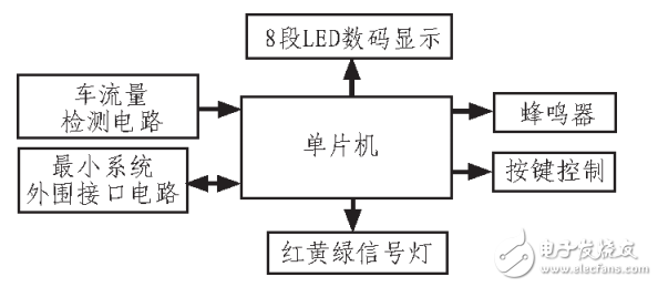
1. Overall block diagram design and principle of traffic control systemThe traffic light control system uses a single-chip microcomputer to directly control the state change of the signal light, and the connected LED digital tube can display a countdown to remind the exerciser. On this basis, the system adds a violation detection circuit and a traffic flow detection circuit to collect data for the single-chip microcomputer, and at the same time, a buzzer is connected. The design takes the single chip as the control core and is connected into the minimum system. The input is generated by the traffic flow detection module, the violation detection module and the button setting module, and the signal status module, the LED countdown module and the buzzer status module accept the output. The overall block diagram of the system is shown in Figure 1.

Figure 1 Overall block diagram of the system
2. System hardware structure and working principleThis design selects AT89C52 single-chip microcomputer and peripheral device to form the minimum control system, 12 LEDs are divided into 4 groups of red, green and yellow three-color lights to form the signal indicator module, 8 LEDs, north and south, each constitutes the countdown display module, and the vehicle flow detection sensor collects the flow. Data, the light sensor captures the violation signal, a number of buttons make up the time setting and mode selection buttons and emergency buttons, etc., and an alarm is made with a buzzer.
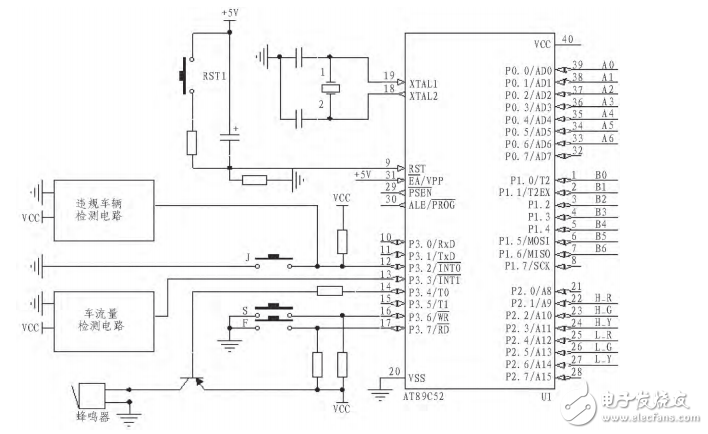
The system hardware circuit consists of a single-chip microcomputer as the core, which constitutes a closed-loop control system that collects, processes and controls the vehicle traffic. The system hardware circuit consists of a vehicle flow detection circuit, a single-chip microcomputer, a violation detection circuit, a status light, an LED display, a button, and a voice prompter. The general hardware circuit diagram is shown in Figure 2.

Figure 2 overall design circuit diagram
P0, P2 are used to send two LED digital tubes, P1 is used to control red, green and yellow LEDs, XTAL1 and XTAL2 are connected to the crystal clock circuit, RESET pin is connected to the reset circuit, P3.3 is INT1 connected to the violation detection circuit. And P3.2 is INT0 close stop / thing time setting button J, P0.6, P0.7 pick up traffic detection circuit, P3.6 is connected to the north-south time setting button S, P3.7 is connected to the automatic mode selection / return button F , P3.4 is connected to the voice prompter. After the system is powered on or manually reset, the system waits for the mode selection setting button to be pressed. The mode is divided into two types: traffic light time auto and traffic light time setting. If the F key is pressed at this time, it is the automatic mode. If the S key is pressed at this time, it is the time setting mode, press S several times in sequence, and the J key can set the traffic light time in two directions several times, and then Press the F key to confirm. In fact, this process is to set the register that stores the time value, and whether the flag is to be detected and adjusted.
Next, the system must first display the status light and the LED digital tube, send the status code value to the P1 port, send the time value to be displayed to the P0 port and use the P2 port to strobe the display of the LED digital tube. In the cycle of 50ms, the software method is used to time 1s. When it reaches 1s, the time value is reduced by 1, and the LED digital tube is refreshed.
When the time reaches the state for all the time, the next state judgment and connection are performed, and the corresponding status code value and time value of the secondary state are loaded, and two external interrupts are turned on, one of which is an illegal signal or a no-stop signal input. The signal is valid, the interrupt starts, enter the interrupt service subroutine, turn on the buzzer to disable all traffic, when the F key is pressed, the interrupt ends and returns. The second is the traffic flow detection signal input. If the vehicle is detected to pass, the corresponding interrupt subroutine is entered, the counter for storing the traffic flow is incremented by 1, and then the interrupt ends and returns.
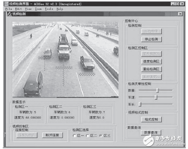
3. Each control module 3.1, vehicle detection moduleThis design adopts the traffic flow detection of video images. The basic idea is to set a fixed area on each lane in the video picture as a virtual detection line, process the image in the area, complete the acquisition of vehicle information, and the working principle of vehicle flow detection. The figure and traffic flow detection diagram are shown in Figures 3 and 4, respectively.

Figure 3 Working principle of traffic flow detection based on video image

Figure 4: Traffic image detection map based on video image
SUNLUX IOT Technology (Guangdong) INC. , https://www.sunluxbarcodereader.com