The PLC program design generally adopts the intuitive method, which means that it is based on the learning experience of the circuit designer itself, which is more subjective and direct. It is necessary to go through a trial and error period of the scorpion, and the program can be debugged to meet the required function or action requirements; therefore, the designed program varies from person to person, except for the original programmer. It is not easy for maintenance personnel to understand the operation process, that is, the program is less readable. But the programming is actually a bit of a slogan, but the books in the workshop rarely mention this part. Let's take the mood of the savage to expose, take the "three-phase induction motor fault alarm control" circuit as an example, the process of converting from the traditional electrician diagram to the ladder diagram, talk about the program design, I believe that the relevant loop conversion or programming You may be permitted to bypass the class.
1, traditional electrician diagram
A known three-phase induction motor fault alarm control circuit, the conventional electrician diagram, is shown in FIG.
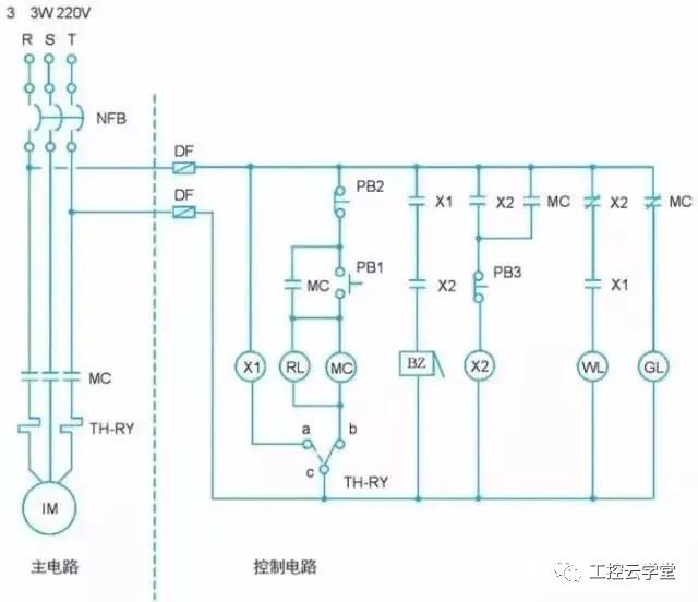
Figure 1 Three-phase induction motor fault alarm control circuit diagram
2, the action description
1. When the power is normal, only the green light gl is on and the motor does not operate.
2. Press the start button pb1, the electromagnetic contactor mc acts, the motor runs immediately, the indicator light rl is on, and the green light gl is off.
3. Press the stop button pb2, the electromagnetic contactor mc is powered off, the motor stops running, the indicator light rl is turned off, and the green light gl is on.
4. During operation of the motor, due to overload or other faults, the accumulated heat electrode th-ry acts, the motor stops running, the buzzer bz issues an alarm, the indicator light rl goes out, and the green light gl lights up.
5. Press the button switch pb3, the buzzer bz stops the alarm, the white light wl lights up, the green light gl lights up, and the red light rl goes out.
6. After the fault is removed, press the heat-collecting power th-ry return lever, then the white light wl goes out, the green light gl lights up, the red light rl goes out, and the motor can be restarted.
3, i / o coding
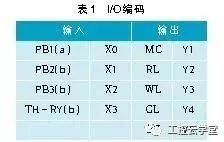
With plc, software wiring is used instead of hardware wiring. In the traditional electrician diagram, the main circuit is not replaced by plc; the part that plc can replace is the control circuit. The first step in converting a traditional electrician diagram into a ladder diagram is i/o coding, which is to determine the input/output component of the conventional electrician diagram by first determining the external input/output terminal number it is intended to correspond to in plc, and The external input component wiring method is a/b contact, as shown in Table 1.
(a): External pick-up point wiring
(b): Externally adopting b-contact wiring
4, plc external wiring diagram
The input/output components are i/o coded, and the external input components are determined by a/b contact wiring. The external wiring diagram of plc is shown in Figure 2. The figure shows the Fengqi vigor-vb series plc model, which uses npn wiring, that is, the 24v terminal is connected with the s/s terminal.

Figure 2 plc external wiring diagram
5, plc ladder diagram
The programming steps for converting a traditional electrician diagram into a ladder diagram are as follows:
(1) Directly convert the control circuit in the electrician diagram into a corresponding step diagram. Since the plc ladder diagram states that the contacts are in front, the output coil must be at the end of the loop. Therefore, the electrician diagram must first be redrawn, and the position of the joint and the output coil in the figure should be changed moderately to meet the requirements of the plc step diagram, and the electrician diagram after re-rendering is shown in Fig. 3.
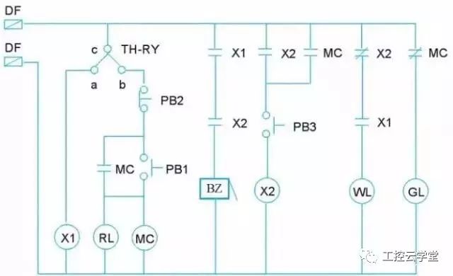
Figure 3 Electric drawing after redrawing
(2) Replace the input/output components in the electrician diagram with the i/o coded component number. It should be noted here that the th-ry ca contact and the cb contact should be independent, and each becomes a control loop, such as Figure 4 shows.
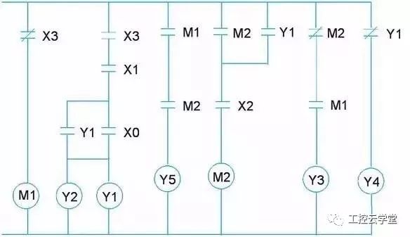
Figure 4 i/o coded electrician
(3) Turn the electrician diagram shown in Figure 4 to the left by 90°, then vertically upside down (upsidedown) to become the plc ladder diagram, but because:
(1) y1, x0 contacts,
(2) The output coils y1 and y2 do not conform to the general programming software format, so they must be properly corrected, as shown in the right side of Figure 5.

Figure 5 Moderately flipped and corrected ladder diagram
※If you use visio to draw an electrician diagram, it will be easy to rotate 90° to the left and then flip it vertically.
(4) The ladder diagram drawn by the programming software, as shown in Fig. 6, is exactly the same as the stepped diagram which is moderately flipped and corrected.
Figure 6 ladder diagram of programming software drawing
6, instructions
Convert the ladder diagram to an instruction as follows:
7, plc conversion wiring and ladder diagram
The traditional electrician diagram completes the conversion of the plc external input/output wiring and ladder diagram. Use the software program to replace the plc external input/output wiring and ladder diagram after the hardware wiring, as shown in Figure 7 below.
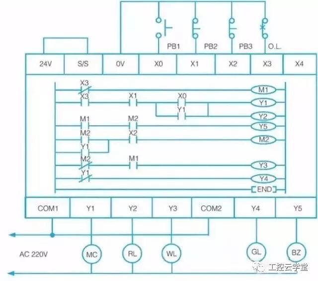
Figure 7 plc replaced by software program after hardware wiring
8. Conclusion
Plc's research and development aims to replace the relay-based sequential control, that is, to use software programs to replace the hardware wiring, so as long as the software program is changed, the order of control can be changed, and the different requirements of control can be easily achieved. The general plc is developed based on the traditional relay control loop, and the contacts and coils of the relay are symbolized. After being converted into a general ladder diagram or command, the control can be realized. However, the control loop thus completed is based on the learning experience of the circuit designer itself, and is more subjective and direct. The general user often does not understand the action flow, that is, the readability of the program is low.
Liquid Crystal Display For Vehicle Use
Dongguan Yijia Optoelectronics Co., Ltd. , http://www.everbestlcdlcm.com