High-performance MEMS accelerometers provide a low-cost solution for a variety of integrated inertial measurement applications. Specific examples include: navigation and AHRS systems, vibration monitoring for machine health detection, structural health monitoring of infrastructure, and tilt monitoring for platform stabilization, downhole directional drilling, construction industry graders and survey equipment High-precision inclinometer for measuring the inclination of the boom of the flat and crane stability system.
In most of these cases, the accelerometer will experience vibrations of different magnitudes. Another different aspect of these applications is the frequency component of the vibration. Vibration combined with sensor and system error sources can cause vibration correction, which is an important indicator of high performance accelerometers.
This article describes how vibration correction occurs in MEMS accelerometers and discusses various techniques for measuring this parameter. As a case study, this article will discuss the vibration correction of the ADXL355 low-noise, low-power accelerometer. Low vibration correction errors and all other features make this device ideal for these precision applications.
Source of vibration correction
The vibration correction error (VRE) is the response of the accelerometer to alternating vibration (rectified to direct current), which is manifested as an abnormal offset of the accelerometer offset. In applications such as inclinometers, this is a significant source of error because the accelerometer's DC output is the target signal, and any change in the offset can be misinterpreted as a dip change, causing the error to pass down all the way, causing a safety system error. Triggering, platform stabilization or excessive compensation of the drill collar alignment mechanism.
The VRE is highly dependent on the vibration characteristics experienced by the accelerometer. The vibration modes applied to the accelerometer by different applications may be different, and thus the VRE may be different. There are several mechanisms for vibration correction, and two of them are discussed in this article.
Asymmetric rail
The first mechanism is an asymmetric rail. Gravity produces a static acceleration field that has an offset in the measurement range when the accelerometer sensitive axis is vertically aligned. When the 2g full-scale sensor is aligned with the gravitational acceleration, only 1 g of peak vibration will be measured, otherwise the response will be clipped. The average of the symmetrical excitation signals above 1 g will not be zero because the level will be clipped in the direction of an additional 1 g of acceleration. In Figure 1, an excitation vibration signal is applied to a 2 g full-scale sensor. When the vibration is 0.3 g rms (between 300 and 600 samples), there is no observable offset in the offset. However, when the vibration is 1 g rms (between 600 and 1000 samples), the VRE is approximately –100 mg.
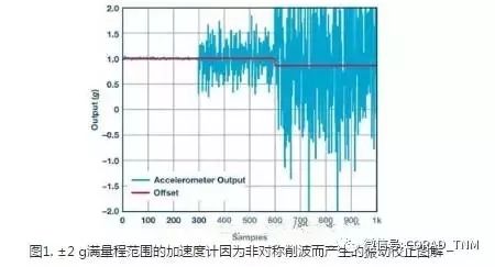
VRE can be modeled as the average offset of a truncated distribution, limited by the full scale range of the accelerometer. When the sensor is subjected to random vibration in a 1 g field, the input excitation signal can be modeled as a normal distribution with an average value μ = 1 g and a standard deviation σ = X, where X represents the input vibration amplitude rms value. The sensor output is modeled as a double-truncated normal distribution with the lower and upper bounds of the output values ​​as –R and +R, respectively, where R is the maximum range of the sensor. The average of this double truncated normal distribution is calculated as follows:

Scale factor nonlinear error
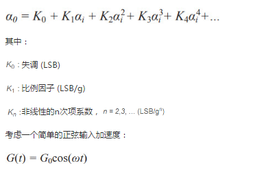
The nonlinear error is the deviation of the accelerometer output from the best-fit straight line in the working range. This deviation is often expressed as a percentage of the full-scale output range. The nonlinearity of the accelerometer can cause VRE as follows: A common model for describing accelerometer nonlinearity is the nth degree polynomial. The output ao (LSB) can be expressed as a function of input ai (g):
The output is equal to the sum of the time averages of all components on the right side of the above equation. The average of odd-numbered terms is zero. The average value of the even-numbered term is taken, and the time average of the output is:
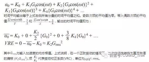
Vibration Correction Amplitude and Frequency Correlation The vibration amplitude is very small. VRE is mainly based on sensor nonlinearity and can be represented by VRC: VRE = VRC × However, when the vibration amplitude is greater than the full-scale range, VRE is often asymmetrical as described in the above section. Clipping dominated. In addition, as previously mentioned, any non-zero offset of the accelerometer output can also cause asymmetric clipping. Most MEMS accelerometers designed for industrial applications have built-in fail-safe circuits that turn off the sensor bias circuit to prevent damage to the sensing components when there is significant vibration. When the amplitude of the vibration is large, this characteristic may further cause an abnormal offset in the offset, which deteriorates the VRE.
VREs often have a strong frequency dependence due to various resonances and filters in the device. Due to the two-pole response of the resonator, at the resonant frequency of the sensor, the MEMS sensor resonance amplifies the vibration, the amplification ratio is equal to the resonance quality factor, and the vibration is suppressed at higher frequencies. For sensors with a higher resonance quality factor, the greater the vibration amplitude, the larger the VRE. Due to the integral effect of vibration in the high frequency band, a larger measurement bandwidth also causes a higher VRE. The analog and digital filters implemented in the signal processing circuit suppress the out-of-band vibration peaks and harmonics at the output, but have no significant effect on the VRE because the vibration input is rectified to an even DC signal by an even number of times.
Measuring vibration correction
Once the accelerometer is deployed on site, the VRE cannot be compensated in real time. In some applications, a small DC offset in the vibration-induced offset can be tolerated, for which the VRE can be measured to estimate the error in the accelerometer output to determine if the VRE is within the allowable limits. In any vibration measurement, the vibrating table and the test fixture must be flush, and a precision vibrating table must be used to suppress errors caused by vibration of the vibrating table, offset, and structural resonance. In addition, the test fixture must have adequate stiffness to ensure that the fixture resonance frequency is far from the accelerometer bandwidth and vibration curve band. The lowest resonant frequency of the optimal fixture design should be approximately 50% higher than the highest vibration frequency.
Sinusoidal vibration characteristic curve
The sinusoidal vibration method is the most commonly used and most widely discussed method in the literature and has been incorporated into IEEE Standard 1293-1998. The general procedure is to apply a sinusoidal vibration input to the accelerometer and then measure the relationship between the offset offset and the rms amplitude. The VRC can be estimated by applying a least squares method to this data:

Since the amplitude can be well controlled and the accelerometer is not clipped, the VRC can be accurately measured by a variety of methods. This test can also be used to identify and quantify the effects of device resonance on VRE. However, it can only test one frequency at a time, and to fully measure sensor performance, multiple frequencies within the accelerometer bandwidth must be tested separately.
Random vibration characteristic curve
VRE can also be measured using random vibration inputs. In general, the actual vibration is not as cyclic or predictable as the sinusoidal vibration characteristic, so the performance of the accelerometer in most applications can be measured by this method. By quantifying the offset offset of the wideband excitation over a wide frequency range, this approach is more suitable for incorporating all scrambling at the same time and exciting all device resonances. However, it does not guarantee the peak-to-peak vibration amplitude, and thus the obtained VRE is an average value over the frequency range.
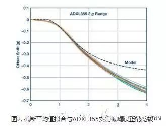
Figure 2 compares the truncated average model and the measured VRE for the ADXL355 Z-axis sensor configured for the ±2 g range. In the measurement, the Z-axis is aligned with gravity (1 g field) and a random vibration characteristic (50 Hz to 2 kHz band) is applied using an Unholtz-Dickie shaker. The vibration amplitude is measured using a reference accelerometer (PCB Piezotronics Model 352C23); the offset offset is measured when the vibration amplitude is increased above the full-scale range. The truncated mean model (fitting to 2.5 g truncation) fits well with the measurements. Due to mechanical sensor overhead and output bandwidth limitations (the accelerometer bandwidth in the measurement data is 1 kHz, but the model does not consider bandwidth), the truncation is expected to deviate relative to the set full-scale range. When the vibration level reaches 8 g, the over-range protection circuit in the ±2 g range is activated. The crest factor of the Gaussian distribution vibration is about 3, so after more than 2.5 g rms, the measured performance begins to deviate significantly from the model.

Other factors affecting VRE
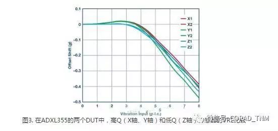
MEMS sensor resonance affects the vibration correction of the accelerometer. A high quality factor causes the vibration signal whose frequency is close to the resonant frequency of the sensor to be amplified, causing a large VRE. This can be seen by comparing the VRE performance of the Z-axis sensor with the XXL and Y-axis sensors of the ADXL355 (±8 g range, 1 kHz bandwidth); Figure 3 shows that the VRE of the X-axis and Y-axis sensors peaks around 3 g rms Because its Q is higher than the Z-axis sensor.
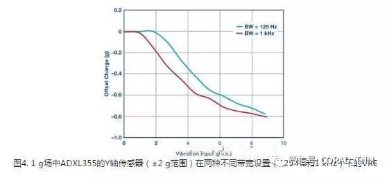
The use of an unnecessarily large bandwidth also causes the accelerometer to average the higher frequency components, which adversely affects the VRE.
Conclusion
Choosing the right bandwidth for the accelerometer to suppress high frequency vibrations can avoid many vibration related problems. By amplifying the vibration coupling at resonance, packaging factors such as package and mounting resonance also affect the VRE. Ensuring that the package has the proper stiffness and allowing the package and mounting resonant frequencies to be outside the accelerometer bandwidth is key to achieving good vibration correction performance.
In summary, vibration correction error (VRE) is an important indicator of MEMS accelerometer. This paper discusses the main sources of VRE and the corresponding measurement techniques. This effect should be considered when designing MEMS accelerometers for DC measurements in high vibration environments. The ADXL355 offers excellent vibration correction, long-term repeatability and low noise performance with a small footprint.
Storage Battery,Auto Battery,Car Battery,Autocraft Battery
SUZHOU DEVELPOWER ENERGY EQUIPMENT CO.,LTD , https://www.fisoph-power.com