defined as:
1. In an AC circuit, the cosine of the phase difference (Φ) between voltage and current is called the power factor and is represented by the symbol cosΦ. In terms of value, the power factor is the ratio of active power to apparent power, ie cosΦ=P/ S
2. The magnitude of the power factor is related to the load nature of the circuit. For example, the power factor of a resistive load such as an incandescent bulb or a resistance furnace is 1. The power factor of a circuit having an inductive or capacitive load is generally less than one. Power factor is an important technical data for power systems. Power factor is a factor that measures the efficiency of electrical equipment. The low power factor indicates that the reactive power of the circuit for alternating magnetic field conversion is large, thereby reducing the utilization rate of the device and increasing the power loss of the line. Therefore, the power supply department has certain standard requirements for the power factor of the power unit.
In power systems, there are many motors and other devices with coils (windings) that consume a portion of the electrical power to create a coil magnetic field in addition to a portion of the electrical power from the power source. This is additionally added to the negative tank of the power supply. The power factor cosØ (also called the force rate) is the proportion of the active power in the total electric power.
In the theoretical formula, the cosØ in P=U*I*cosØ in the active power expression is the power factor, and the power factor is less than or equal to 1. The magnitude of the power factor indicates the degree of utilization of the power supply, and its height determines the voltage of the monthly circuit terminal and The phase difference between the currents. When the cosØ is less than 1 in the circuit, the energy exchange occurs and the reactive power Q=UIsinØ.
Therefore, in the calculation process, you can pass cosØ=P/S, tgØ=P/Q (where: P is called active power (KW), Q is called reactive power (Kvar), and S=U*I is called apparent power. (KVA)), in practice, the available power value instead of the corresponding power.
We know that all generators are rotating machines and the resulting voltage is a sine wave. This is what we call AC. One of the advantages of AC power is that it can be changed by a transformer to change its voltage, and it can be raised to hundreds of thousands of volts for long-distance transmission to reduce the loss in transmission. After the destination, it will be reduced to become our common city. Electricity. Our current utility is 220V, 50Hz AC. In electrical engineering, alternating current can be represented by vectors. The vector can represent voltage as well as current. For a purely resistive load, the voltage and current are in phase, while for a pure capacitive load or a purely inductive load, the current and voltage are out of phase, but have a phase angle of 90 degrees, or phase difference. In a purely inductive load, the voltage on it is 90 degrees ahead of the current, while the voltage on the pure capacitive load is 90 degrees behind the current.
If we use a waveform, the voltage is usually expressed as a cosine wave. If the current lags behind the voltage, it is an inductive load. The leading voltage is a capacitive load.
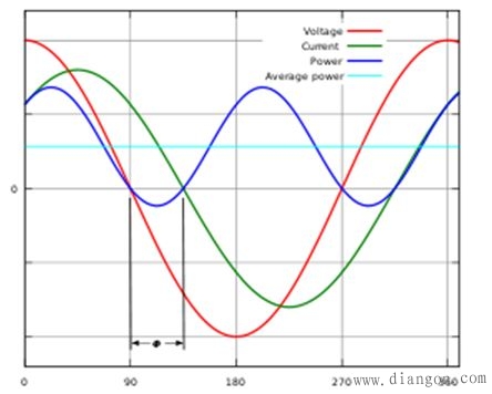
Figure 1. Relationship between AC voltage and AC current for inductive loads
Because virtually no pure and pure capacitors exist, the actual load can only be called an inductive load or a capacitive load. At this time, there is an angle φ between the AC voltage and the AC current. For the inductive load, we call this angle φL, and for the capacitive load, the angle is called φC. (See Figure 2)
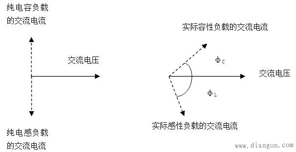
Figure 2. Vector representation of inductive and capacitive load voltages and currents
The power is equal to the product of voltage and current, but only for purely resistive loads (voltage and current are in phase), and for inductive or capacitive loads, the vector of current is projected onto the voltage vector (horizontal axis). That is, multiply by cosφL or cosφC. We usually refer to this cosφL or cosφC as the power factor.
However, since this angle can be positive or negative, the power factor can also be positive (inductive load) or negative (capacitive load).
But when we use vectors to represent voltage and current, the premise is that their frequencies must be identical. And it is in a linear system.
In linear systems we also express the power factor as the ratio of active power to apparent power. The so-called active power is the product of the voltage and current rms value of the same phase as the current. The apparent power is the "power" obtained by directly multiplying the effective values ​​of the voltage and the current without considering the phase difference therebetween. The ratio of the two is obviously the cosine cosφ of the phase angle mentioned above.
Cable Box,Junction Boxes,Cable Connection Box,Waterproof Cable Box
Jiangmen Krealux Electrical Appliances Co.,Ltd. , https://www.krealux-online.com