1 Overview
This article refers to the address: http://
With the booming of the automotive industry, in-vehicle infotainment systems are becoming an important part of automotive intelligence. While providing consumers with more advanced comfort, entertainment and information, car infotainment systems as a high value-added electronic product of the vehicle account for a larger proportion of the car, and the integrated function is Simple audio equipment, CD equipment, and radio equipment have gradually expanded into multimedia information interaction devices that integrate video entertainment, car navigation, and wireless communication.
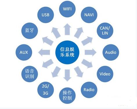
Figure 1 Overview of infotainment system features
As can be seen from the figure, an in-vehicle infotainment system has functions such as audio playback, video image playback, broadcasting, navigation, Bluetooth, voice recognition, and mobile communication, and the in-vehicle infotainment system is used as a node of the entire vehicle electrical and network. It is responsible for displaying and feedbacking the status and information of the vehicle.
2. Test requirements
As mentioned above, the important role played by in-vehicle infotainment equipment in the entire vehicle provides the driver with the most intuitive vehicle comfort, entertainment and quality experience. However, due to the limitations of testing techniques, means and conditions, the in-vehicle infotainment system has many problems with its functions and performance compared with other traditional electronic control units, such as: pop-up of audio playback, sluggish response of touch screen, display error of interactive interface. The problems of low navigation and positioning accuracy and accurate low voice recognition all restrict the quality improvement of information entertainment and the user experience.
Therefore, functional and performance levels must be tested for each function during the product development phase. The functions of the infotainment system involve the integration of human-computer interaction, audio and video signals, wireless signals, hard-wire signals and bus signals. Therefore, the test requirements under laboratory conditions are extensive and complex. The following figure shows the basic test requirements for the functions and performance of the in-vehicle infotainment system.
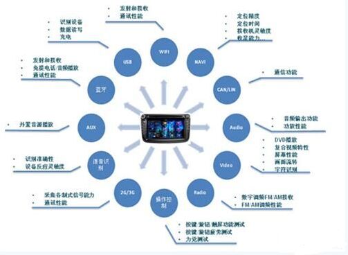
Figure 2 Information Entertainment System Test Requirements
The chart shows several information entertainment system test contents such as:
1. For human-computer interaction, there are both screen flow and character recognition functional tests, as well as image brightness, chrominance, signal-to-noise ratio and other performance levels.
2. For audio system, there are audio output function verification, audio performance, and power amplifier performance tests;
3. Data reading and writing, device identification, charging current and other tests for USB functions;
4. For the radio system, there are FM/AM receiving function test, and FM/AM frequency modulation performance test;
5. Tests for navigation systems include positioning accuracy, positioning time, and ability to collect stars;
6. Mobile phone interconnection function test for Bluetooth function, including test of transmission and reception performance.
In summary, the information entertainment system testing needs are wide-ranging, complex and diverse, and the testing is time-consuming and labor-intensive. In the face of such testing challenges, traditional testing is inefficient, time-consuming and labor-intensive, and can no longer meet the needs of modern automated testing. A comprehensive software and hardware platform with comprehensive testing capabilities to solve the test challenges of the in-vehicle infotainment system on the road of quality improvement.
3. Solution
Hengrun Technology's in-vehicle entertainment information test system based on machine vision, robot and hardware-in-the-loop simulation technology, used for testing automotive functions and performance projects, using test systems to simulate the wired and wireless signals required for in-car entertainment systems. Simulate the real use environment of the car entertainment system in the laboratory environment. The test equipment can also simulate various operational control signals (including touch screen, remote control, buttons and voice) of the in-vehicle entertainment system, automatically execute test scripts for various functions and performances, and automatically generate test reports.
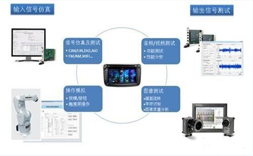
Figure 3 Information Entertainment Test System Solution
As shown in the figure above, the test system provides a closed-loop test environment for in-vehicle infotainment systems:
Input signal simulation
a) Hard line signal simulation
b) bus signal simulation
c) touch operation simulation
d) voice signal simulation
e) RF signal simulation
2. Output signal acquisition and testing
a) Hard line signal acquisition
b) bus signal analysis
c) image signal feature extraction
d) audio signal analysis
e) RF signal reception and analysis
The simulation and simulation of the working environment of the vehicle-mounted multimedia device are realized. The system realizes the automatic test environment in the laboratory condition by providing robot touch and image acquisition, instead of manually operating and observing the information entertainment system. The development and performance testing of the functionality of the entertainment system provides favorable support and means.
3.1. Touch operation simulation
The system integrates 6-degree-of-freedom industrial robots, and users can complete various touch operation settings for in-vehicle infotainment devices without programming, such as mechanical buttons, knobs, touch screens, double-clicks, drag and so on. It also includes a variety of parameter configurations, which can set the number of touches, contact time, rotation angle, and so on.
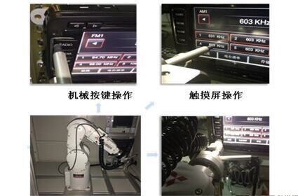
Figure 4 robot touch simulation
3.2. Interface image recognition
The system replaces the human eye recognition function based on machine vision. The software can effectively identify the graphic symbols, character numbers, pointers, color brightness, etc. of the infotainment system display interface through image acquisition and analysis functions, and realize the flow of information and information on human-computer interaction. Tests for display, feature determination, etc. are required.
As shown in the figure below, the system takes the image to be tested to obtain image information, and acquires image feature information such as “101.9†and “fast forward arrow†in the expected area as the judgment basis.
Figure 5 image feature recognition
3.3. Conventional Signal Simulation and Acquisition
The system is based on hardware-in-the-loop technology, which can simulate and collect various types of sensors, actuator signals, network virtual nodes, etc. based on hard lines and buses, and constitute the virtual vehicle environment required by the controller to be tested, without having to be in a real car or On the prototype. This kind of test is systematic, safe and reliable, even if the test exceeds the limit conditions, it will not cause any damage, and it is easy to reproduce the error of the controller to be tested. Simplifies the testing process and improves the efficiency of testing.
Figure 6 hardware in-loop test
3.4. RF Signal Simulation and Analysis
Classic Ethernet uses a long cable meandering around the building, and this cable connects all the computers. The architecture of classic Ethernet is shown in the following figure "Ethernet":
Physical layer
Each version of Ethernet has a maximum cable length limit (that is, the length that does not need to be amplified). Signals within this range can be transmitted normally, and signals beyond this range will not be transmitted. In order to allow the construction of a larger network, multiple cables can be connected with repeaters. A repeater is a physical layer device that can receive, amplify, and retransmit signals in both directions.
On these cables, the transmission of information uses Manchester encoding.
MAC sublayer
Classic Ethernet uses 1-adhere to the CSMA/CD algorithm, that is, when the station has a frame to send, it must listen to the medium, and send it immediately once the medium becomes free. Monitor whether there are conflicts on the channel while they are being sent. If there is a conflict, immediately terminate the transmission, and send a short conflict enhancement signal, and then wait for a random period of time before resending.
The development of Ethernet is very fast, starting to evolve from the typical Ethernet structure of a single long cable. The problems of a single cable, such as finding out the connection-related problems such as broken or loose locations, have driven people to develop a different type of wiring mode. In this mode, each station has a dedicated wire connected to a central hub. The hub simply connects all the connecting wires electrically, like soldering them together. Hubs cannot increase capacity because they are logically equivalent to classic Ethernet with a single cable. As more and more stations join, the share of fixed capacity shared by each station decreases. Eventually, the LAN will be saturated.
There is another way out to handle the ever-increasing load: switched Ethernet. The core of switched Ethernet is a switch, which contains a high-speed backplane that connects all ports. From the outside, switches look like hubs. They are a box, usually with 4-48 ports, and each port has a standard RJ-45 connector for connecting twisted-pair cables. The switch only outputs the frame to the port where the frame wants to go. A machine can be added or deleted by simply plugging in or unplugging the cable, and since the flaky cable or port usually only affects one machine, most errors are easy to find. This configuration mode still has the problem of a shared component failure, that is, the failure of the switch itself: if all stations lose network connectivity, the IT staff knows how to solve this problem: replace the entire switch.
Rf Port Onu,Pon Technology,Catv Port
Shenzhen GL-COM Technology CO.,LTD. , https://www.szglcom.com