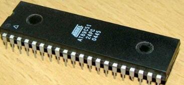
MCU AT89C51 P1 port connected to eight light-emitting diodes, so that the eight light-emitting diodes can be double-shifted to the left and then double-shift right lamp to form the effect of the deuterium lamp, so after the cycle 5 times full off, delay 0.5S. Move the lamp to the right to form the effect of a xenon lamp. After 5 cycles, it will be completely extinguished. Delay 0.5S.

Source code
ORG 0000H
MOV A, #11111100B
Start:
MOV P1, A
CALL delay
RL A
RL A
INC R0
CJNE R0,#4,start
MOV R0, #00H
s:
RR A
RR A
MOV P1, A
CALL delay
INC R0
CJNE R0, #4,s
MOV R0, #00H
LJMP start
Delay: MOV R5, #100
K1: MOV R6, #250
K2: MOV R7, #250
K3: DJNZ R7,k3
DJNZ R6,k2
DJNZ R5,k1
RET
END
SCM water assembly language source code (2)MCU AT89C51 P1 mouth and P2 mouth, respectively, connected to the eight light-emitting diodes, P2 eight lights to achieve left, delay 0.5S, requires the first time left, P1.0 corresponding lights, P2 mouth lamp left second The next time, P1.1 corresponds to the light, so it continues until all lights are turned off after eight left shifts.
ORG 0000H
MOV R0, #11111110B
Start: MOV A, #11111110B
MOV P2,A
s: CALL delay
RL A
MOV P2,A
CALL delay
CJNE A, #01111111B,s
MOV A,R0
MOV P1, A
RL A
MOV R0,A
JMP start
Delay: MOV R5, #100
K1: MOV R6, #250
K2: MOV R7, #250
K3: DJNZ R7,k3
DJNZ R6,k2
DJNZ R5,k1
RET
END
SCM water assembly language source code Daquan (3)The P2 port of the single-chip microcomputer AT89C51 is connected with 8 dial switches; the P0 port is connected with 8 LEDs. Before the DIP switch is closed, the 8 LEDs are all on. When the DIP switch P2.0 is closed, the LED corresponding to P0.0 is off, and so on.
Source code:
ORG 0
MOV A, #00000000B
MOV P0,A
MOV P2, #0FFH
LOOP: MOV A, P2
CPL A
MOV P0,A
JMP LOOP
END
SCM water assembly language source code Daquan (4)The P2 port of the single-chip microcomputer AT89C51 is connected with 8 dial switches; the P0 port is connected with 8 LEDs. After the DIP switch is closed, the 8 LED lights are all left after being shifted left 3 times. When the DIP switch P2.0 is closed, the LED corresponding to P0.0 is off, and so on. The delay is 0.2S.
Source code:
ORG 0
MOV R1, #3
LOOP1: MOV R0, #8
MOV A, #11111110B
LOOP2: MOV P0,A
RL A
CALL D200MS
DJNZ R0, LOOP2
DJNZ R1, LOOP1
MOV A, #00000000B
MOV P0,A
MOV P2, #0FFH
LOOP: MOV A, P2
CPL A
MOV P0,A
JMP LOOP
D200MS:
MOV R7, #250
D1: MOV R6, #200
D2: MOV R5, #2
DJNZ R5, $
DJNZ R6, D2
DJNZ R7, D1
RET
END
SCM water assembly language source code (5)The P2.0, P2.1, and P2.2 ports of the microcontroller AT89C51 are connected to a push button switch, and the P1 port is connected to the decoder 7447, and the output of the 7447 is connected to the common anode LED digital tube. Click the button corresponding to the P2.0 port, the digital tube displays the number “0â€; press the corresponding button of the P2.1 port, the digital tube displays the number “8â€; press the corresponding button of the P2.2 port, the number displayed by the digital tube is closed.
Source code:
ORG 0000H
START: MOV P2, #0FFH
LOOP: JNB P2.0,ON
JNB P2.1, ON8
JNB P2.2,OFF
JMP LOOP
ON: MOV P1, #00H
ON_1: JB P2.0, LOOP
JMP ON_1
ON8: MOV P1, #08H
ON_8: JB P2.1, LOOP
JMP ON_8
OFF: MOV P1, #0FFH
OFF_1: JB P2.2, LOOP
JMP OFF_1
END
SCM water assembly language source code (6)The P0 of the one-chip computer AT89C51 connects 8 LEDs, use INT0 to produce and cut off. When the main program is executed normally, the 8 LEDs of P0 port are shifted to the left. When entering the interrupted state, the eight LEDs of port P0 will become a single lamp to the right, and after three cycles, the state before the interruption is resumed, ie, the eight LED single lamps will continue to be shifted to the left. The delay is 0.5S.
ORG 0000H
JMP main
ORG 0003H
JMP int_0
Main:
SETB IT0
SETB EX0
SETB EA
MOV A, #11111110B
s: RL A
MOV P2,A
CALL delay
JMP s
Delay:
MOV R7, #100
D3: MOV R6, #200
D2: MOV R5, #250
D1: DJNZ R5,d1
DJNZ R6,d2
DJNZ R7,d3
RET
Int_0:
MOV P2,A
MOV R0, #24
k: RR A
MOV P2,A
CALL delay
DJNZ R0,k
MOV R0, #24
RETI
END
There is a rule, custom laptop is called programming laptop cause nearly 90% is used for projects. 15.6 inch laptop for coding and programming is usually equipped with 10th or 11th cpu, 2gb or 4gb graphics optional. 15 inch laptop untuk programming is used on big tender or group for a special jobs. 15.6 inch programming laptop under 30000 is a more competitive one for business or high school students or teachers.
However, here is the recommended laptop for programming, especially for heavy office jobs or university coursework, since double heat-releasing, metal body, bigger battery, FHD screen, high-level cpu, etc. Build the deep and stable foundation to enjoy smooth running experience. Your clients will satisfy it`s excellent performance. Of course, there are other lower specification with tight budget.
As a entry windows laptop for programming, this 14 inch celeron Education Laptop is the most competitive and hottest device for elementary project.
Any other special requirements, just contact us freely.
Programming Laptop,Laptop For Coding And Programming,Programming Laptop Under 30000,Recommended Laptop For Programming,Windows Laptop For Programming
Henan Shuyi Electronics Co., Ltd. , https://www.shuyiaiopc.com