The connecting wires are widely used to connect the lead terminals of the chip and the external pins of the semiconductor device. The wires used for the connections are typically made of gold because gold resists oxidation and is highly conductive, and gold can be used to connect IC lead terminals and device pins relatively easily.
The method of replacing copper wires with copper wires is gaining momentum because copper has excellent electrical and thermal properties, relatively less intermetallic growth and higher mechanical stability.
In devices with large DC currents such as power management ICs, a large number of wires are used to conduct this current. These extra wires help to improve DC drop performance and reduce the risk of wire blown or melt caused by large currents and the associated heat (Joule heat generation). Unfortunately, there is no method or method of analysis for estimating the number and size of wires for a given application. The number of wires used is too large, increasing chip area and cost, or too little, resulting in reliability risks and device failure.
This article explores a method for estimating the ability of wires of different sizes and types to handle DC current. This article also provides guidelines that will help product designers estimate the optimal number of wires required for a particular application.
Estimating theoretical current carrying capacity
The classical design equation for wire fuses was derived from WH Pris (1884, known as the Pris equation) and is only applicable to wires in free air.
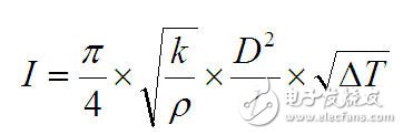
This equation reveals the relationship between the fusing current (in amps) and the wire diameter (in inches) as shown below.
i=kD3/2
Where i is the DC or RMS current; k is a constant, the value depends on the wire material, for gold and copper wires, k = 10, 244; D = wire diameter (in inches).
The limitation of this equation is that it only applies to wires in free air. In addition, it does not consider the length of the conductor. The current carrying capacity of the wire is affected by the length and decreases with increasing length.
Modified Pris equation
In order to solve the above limitations, the Pris equation has been modified to reflect the typical application with a larger constant k. In typical applications, the wire is sealed with an epoxy-based molding compound. This constant k also reflects the effect of wire length on the current carrying capacity of the wire. When the length of the conductor is ≤0.040", the k value of the gold and copper wires is 30,000, and when the length of the conductor is 0.040", the k value is 20,500.
The equations mentioned in the military specification (MIL-M-38510J) are based on the modified Pris equation.
Table 1 lists the current carrying capabilities of the two types of conductors calculated using the two versions of the Pris equation.
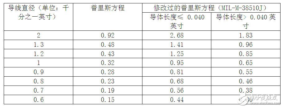
Table 1 Current carrying capacity calculated based on the Pris equation
Even with the modified Pris equation, there are still limits:
The current carrying capacity values ​​shown in Figure 1 are material independent. Compared to gold wires, copper wires have a thermal conductivity of 20% higher and a conductivity of 30%, which theoretically translates into a copper wire capable of delivering more current than a gold wire.
2 This equation does not infer the current carrying capacity of the conductor when the conductor length exceeds 0.040†(approximately 1 mm wire length). Most applications have wire lengths in the range of 2 to 3 mm, sometimes exceeding this range. There are many variations in the current carrying capacity of the wire, and the equation does not take this into account.
In view of the above limitations, it is necessary to find a new method that takes into account known geometrical and material property information as well as limitations imposed by typical applications.
Joule heat generation in a conductor
When a current flows through a non-ideal conductor with a finite resistance, heat is released and the electrical energy is converted into heat by a process called Joule heat generation or resistance heat generation. The amount of heat released is proportional to the square of the current through the conductor and the resistance of the conductor. The three relationships are as follows:
Qgenerated=I2R
For a conductor surrounded by still air, all of the heat generated is dissipated through the conductor without heat being conducted out of the conductor surface. When the following equation is true, the system reaches a steady state:
Qgenerated=Qdissipated
The heat generated is dissipated through the wire by a simple heat transfer process as shown by the following equation:
Qdissipated=kAdt/dx
Where k is the thermal conductivity of the wire; A = the cross-sectional area of ​​the wire; dT = the temperature difference across the wire; dx = wire length.
Rearrange the above equations and simplify them to:
Further simplification:
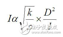
Based on the above relationship, assuming that all other conditions remain the same, the DC or RMS current that the copper wire can handle should be 25% larger than the gold wire.
In most practical applications, heat can be conducted not only through the wire, but also through the epoxy molding compound, which is conducted radially from the surface of the wire. The heat conduction phenomenon after the combination of the two is very complicated, and it is impossible to accurately analyze with the closed-loop equation. Therefore, people use a limited component modeling software with a thermoelectric coupling physics solver to analyze the effects of different wire parameters.
Semiconductor Disc Devices(Capsule Type)
Semiconductor Disc Devices(Capsule Type) is the abbreviation of thyristor, also known as silicon controlled rectifier, formerly referred to as thyristor; thyristor is PNPN four-layer semiconductor structure, it has three poles: anode, cathode and control pole; thyristor has silicon rectifier The characteristics of the parts can work under high voltage and high current conditions, and their working processes can be controlled and widely used in electronic circuits such as controlled rectifiers, AC voltage regulators, contactless electronic switches, inverters, and inverters.")
Used on the PoweN Supply

Semiconductor Disc Devices,Inverter Thyristor,Phase Control Thyristor,Capsule Type Semiconductor Disc Devices
YANGZHOU POSITIONING TECH CO., LTD. , https://www.pst-thyristor.com