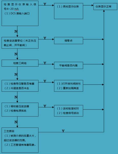
Field instrument failure analysis principle
1. First, before analyzing the field instrument failure, it is necessary to thoroughly understand the production process, production process conditions and conditions of the relevant instrument system, understand the design side and design intent of the instrument system, and the structure, characteristics, performance and parameter requirements of the instrument system. Wait.
2. Before analyzing and inspecting the fault of the instrument system in the field, it is necessary to understand the changes of the production load and the parameters of the raw materials to the on-site operators, check the record curve of the faulty instrument, and conduct a comprehensive analysis to determine the cause of the instrument failure.
3. If the instrument record curve is a dead line (a line with no change at all) is called a dead line, or the record curve is originally fluctuating, it suddenly becomes a straight line; the fault is likely to be in the instrument system. Because most of the current recording instruments are DCS computer systems, the sensitivity is very high, and the change of parameters can be very sensitive. At this point, you can artificially change the process parameters to see the curve changes. If it does not change, the basic conclusion is that the instrument system has a problem; if there is a normal change, it is basically determined that the instrument system has no major problems.
4. When the process parameters are changed, it is found that the recorded curve is abrupt or jumps to the maximum or the most, and the fault at this time is also often in the instrument system.
5. Before the fault occurs, the instrument record curve has been performing normally. After the fluctuation occurs, the record curve becomes irregular or the system is difficult to control. Even the manual operation cannot be controlled. At this time, the fault may be caused by the process operating system.
6. When the DCS display meter is not normal, you can go to the site to check the indication value of the same intuitive meter. If they are very different, it is likely that the instrument system has failed.
In short, when analyzing the cause of the field instrument failure, pay special attention to the changes in the characteristics of the controlled object and the control valve, which may be the cause of the failure of the field instrument system. Therefore, we must comprehensively examine and analyze the two aspects of the field instrument system and the process operating system to check the reasons.
Flow control system failure analysis steps
"
Summary of 414 kinds of fault phenomena handling schemes for 24 types of commonly used instruments and meters...
â€
1. Common faults and analysis of electromagnetic flowmeter
| Serial number | Fault phenomenon | cause of issue | Approach |
| 1 | After working for a period of time, I found that the meter is not working properly. | Is the power supply good? | First check the external condition of the flowmeter, remember to blindly disassemble the flowmeter |
| Whether the pipe leaks | Inspection processing | ||
| In a non-full tube state | Inspection processing | ||
| Is there a bubble in the pipe? | Inspection processing | ||
| Is the signal cable damaged? | Replace the new cable | ||
| Is the converter output signal open? | Inspection processing | ||
| 2 | The signal becomes smaller or suddenly drops | The insulation between the electrodes is deteriorated or short-circuited, and there may be deposited dirt on the inner wall of the measuring tube. | Should be cleaned and wiped the electrode |
| Measuring catheter lining may be destroyed | Should be replaced | ||
| Signal socket may be corroded | Should be cleaned or replaced | ||
| 3 | 4 mA is output when the fluid in the measuring tube is stationary, and the current becomes small or zero when there is flow (debug during commissioning) | When the flowmeter is installed, the flow direction is opposite to the actual flow direction. | Check the flow direction of the flowmeter, change the flowmeter installation direction, or exchange the X and Y wires in the converter. |
| Split type flowmeter A and B or X and Y lines have a set of reverse | Carefully check the excitation and signal lines to correct errors on the wiring | ||
| 4 | The flowmeter only outputs 4mA current (the split type wrong line mainly appears in the debugger) | The measured medium does not actually flow | Take corrective measures to ensure proper flow of media in the measuring tube |
| The excitation part of the converter is in the test state | Insert the shunt on 2, 3 or 3, 4 feet (working status) | ||
| The excitation line and signal line between the split type flowmeter sensor and the converter are connected incorrectly. | When wiring properly, disconnected or shorted, contact the company if in doubt. | ||
| Sensor failure | Faulty contact company | ||
| Converter excitation part circuit failure | Faulty contact company | ||
| 5 | The output signal is unstable (conductivity problem mainly occurs during the debugging period) | The dielectric conductivity is lower than the lower limit of the electromagnetic flowmeter 5us/cm | A medium with too low conductivity cannot be accurately measured with an electromagnetic flowmeter. |
| The medium contains solid particles or slurries | The medium contains solid particles or slurries | ||
| Poor liquid or poor grounding | The insulated pipeline must be equipped with a grounding ring; the flowmeter must be reliably connected to the liquid through the grounding wire; the separate grounding can improve the anti-interference ability of the flowmeter. | ||
| External electromagnetic interference | 1. Keep away from interference sources; 2. Stray current is mainly grounded by good ground. It is best to ground it separately. Do not share grounding with other electrical appliances or instruments. 3. Split-type instrument signal line strengthens the shield, sets the iron pipe, or shields the wire to the other end. | ||
| Flowmeter measuring tube contains a lot of bubbles | Check the pipeline or valve, avoid introducing air into the fluid inlet; install the exhaust valve in a suitable place to eliminate the air in the measuring pipe section; install the flowmeter in a place where it is difficult to collect gas; open the exhaust pipe, downstream of the flowmeter Can be raised appropriately | ||
| The fluid itself is fluctuating or pulsating | Keep the flowmeter away from the pulsation source as much as possible. If necessary, install a steady flow device at the appropriate position of the pipeline to minimize fluid stability. | ||
| There is liquid addition in the upstream main liquid, and it has not been mixed evenly at the flow meter. | There is liquid addition in the upstream main liquid, and it has not been mixed evenly at the flow meter. | ||
| The flowmeter power supply line is parallel to the output signal line or worn in a conduit | Keep the signal output lines from side by side with the AC power line, especially to avoid using the same line. | ||
| 6 | Output signal super fullness value | The actual flow rate is greater than the flowmeter full scale flow (overrange) | Carefully analyze the pipeline, do not rely solely on the empirical value; sometimes the rated flow of the pump can not be used as the sole basis for the flow; properly close the flow to observe the flowmeter output. The commonly used flow exceeds the full scale of the flowmeter, you must contact the company to modify the range. |
| Split type flowmeter excitation, signal line connection error | Correct the wrong wiring | ||
| Flowmeter measuring tube is not full | Make sure the flow meter is always full | ||
| Poor liquid or poor grounding | The insulated pipeline must be equipped with a grounding ring; the meter body must be reliably connected to the liquid through the grounding wire; the separate grounding can avoid the interference introduced by the grounding wire. | ||
| Converter failure | Converter signal amplification, output part check, contact company | ||
| Sensor failure | Contact company | ||
| 7 | The measurement result does not match the actual flow rate. | Rear instrument matching problem | Correct flow and matching problems with the rear instrument or computer |
| The output signal line has a leakage (or a slight short circuit) | Leakage of the current output signal will cause the indicated flow to be too small, and the signal line must be replaced. | ||
| Is the empirical 'actual flow' credible? | Carefully analyze the flow and piping conditions, and seek to compare the reference frame when necessary, and contact the company if necessary. | ||
| Sensor installation is not standardized | Straight pipe section, full pipe condition, air bubbles, liquid pulsation, etc. According to the specification specification installation. | ||
| Electrode surface area scale | Clean the sensor, taking care not to damage the lining | ||
| Process pipe leak or branch pipe | Eliminate valve leakage on the pipeline, branch shunting, etc. | ||
| Sensor insulation drops | Contact the company |
2. Common faults and analysis of vortex flowmeter
| Serial number | Fault phenomenon | cause of issue | Approach |
| 1 | Output signal when there is no flow after power-on | Input shielding or poor grounding, introducing electromagnetic interference | Improve shielding and grounding, and eliminate electromagnetic interference |
| The instrument is close to strong electrical equipment or high frequency pulse interference source | Keep away from interference sources and take isolation measures to enhance power supply filtering | ||
| The pipeline has strong vibration | Take vibration reduction measures to enhance signal filtering and reduce amplifier sensitivity | ||
| Converter sensitivity is too high | Reduce sensitivity and increase trigger level | ||
| 2 | No output signal after power-on | Power failure | Check power and ground |
| Input signal line disconnection | Check signal lines and terminals | ||
| A certain level of amplifier is faulty | Check the working point, check the components | ||
| Detecting original damage | Check sensor components and leads | ||
| No flow or too small flow | Check valve to increase flow or reduce pipe diameter | ||
| The pipe is blocked or the sensor is stuck | Check the cleaning pipe and clean the sensor | ||
| Vortex body scaling | Cleaning vortex generator | ||
| 3 | Output signal is not stable | Strong electrical interference signal | Strengthen shielding and grounding |
| Sensor is contaminated or damp, sensitivity is reduced | Clean or replace the sensor to increase the gain of the booster | ||
| Sensor sensitivity is too high | Reduce the gain and increase the trigger level | ||
| Damaged sensor or poor lead contact | Check sensor and lead | ||
| Two-phase flow or pulsating flow | Strengthen process management to eliminate two-phase flow or pulsating flow | ||
| Pipeline vibration | Take vibration reduction measures | ||
| Process instability | Adjust the installation location | ||
| The sensor is installed with different hearts or gaskets protruding into the tube | Check the installation and correct the inner diameter of the seal | ||
| Upstream and downstream valve disturbance | Lengthen straight pipe or add flow regulator | ||
| Fluid is not filled with tubing | Change the location and method of loading the flow sensor | ||
| Body wrap | Elimination of wraps | ||
| Cavitation | Reduce flow rate and increase pressure inside the tube | ||
| 4 | Large measurement error | Insufficient length of straight pipe | Lengthen straight pipe or add flow regulator |
| Analog conversion circuit zero drift or full scale adjustment is wrong | Calibrate the zero and span scales | ||
| Supply voltage changes too much | Check the power supply | ||
| The meter exceeds the verification period | Timely inspection | ||
| The difference between the inner diameter of the sensor and the pipe is large | Check the inner diameter of the pipe and correct the meter factor | ||
| Install different hearts or seals into the tube | Adjust the installation, trim the gasket | ||
| Sensor contamination or damage | Cleaning replacement sensor | ||
| Two-phase flow or pulsating flow | Eliminate two-phase flow or pulsating flow | ||
| Pipe leak | Exclude leaks | ||
| 5 | Measuring tube leak | In-tube pressure is too high | Adjust tube pressure and change installation position |
| Nominal pressure selection is wrong | Use high-grade nominal pressure sensor | ||
| Seal damage | Replacement seal | ||
| Sensor is corroded | Take anti-corrosion and protection measures | ||
| 6 | Abnormal whistling of the sensor | The flow rate is too high, causing strong vibration | Adjust flow or replace large gauges |
| Cavitation | Adjust flow and increase flow pressure | ||
| Body loosening | Fastening body | ||
| 7 | Traffic accumulation counter does not work | Counter wheel mechanism is not flexible or stuck | Cleaning the counter gear or replacing the counter |
| Counter coil off | Rewind the coil or replace the same spare part | ||
| Coefficient setting and programmer component circuit failure | Repair the corresponding component circuit or replace the corresponding component | ||
| Display board front panel component circuit failure | Repair the corresponding component circuit or replace the corresponding component | ||
| Vortex transmitter has no output | Repair or replace the transmission unit |
3. Rotor flowmeter common faults and analysis
| Serial number | Fault phenomenon | cause of issue | Approach |
| 1 | Pointer jitter | Slight pointer jitter, usually due to media fluctuations | Can be overcome by increasing the damping method |
| Moderate pointer jitter: usually due to media flow conditions | Regenerative or steady flow devices can be used to overcome or increase the rotor flowmeter damping | ||
| Violent pointer jitter: mainly due to medium pulsation, unstable air pressure or other operating conditions of the user, the pressure, temperature, flow rate and the actual state of the rotor flowmeter do not match, there is a big difference. | Adjust the corresponding parameters | ||
| 2 | The pointer stops at a certain position and does not move | Open the valve too fast, causing the stopper to deform and the rotor to be stuck | Slowly open the valve |
| The rotor guide rod is not the same as the stop ring | The instrument is removed, the deformed stopper is removed and shaped | ||
| 3 | Large measurement error | Installation does not meet the requirements | For the vertical installation of the rotor flowmeter to maintain vertical, the inclination angle is not more than 20 degrees; for the horizontal installation of the rotor flowmeter to maintain horizontal, the inclination angle is not more than 20 degrees, the rotor flowmeter around 100mm space must not have ferromagnetic objects, the installation position should be away from the valve Diameter port, pump outlet, process line turning, etc. To maintain the front straight pipe section is 5D, the rear straight pipe section is required to be 250mm. |
| The density of the liquid medium changes greatly | The density of the medium after the change can be brought into the formula, converted into an error correction coefficient, and then the flow measured by the flow meter is multiplied by the coefficient to be converted into a real flow. | ||
| Gas medium is greatly affected by temperature and pressure | Use temperature and pressure compensation to get real flow | ||
| Long-term use and pipeline vibration and other factors cause the rotor flowmeter to sense the loosening of moving parts such as magnetic steel, hands, counterweights, and rotating magnetic steel, resulting in large errors. | You can verify it by pushing the pointer with your hand. First press the pointer to the RP position to see if the output is 4 mA, whether the flow display is 0%, and then verify according to the scale. If the discrepancies are found, the parts can be adjusted. Generally require professional adjustment, otherwise it will cause the position to be lost, need to return to the manufacturer for correction. | ||
| 4 | No current output | First look at the wiring is correct | Correct wiring |
| Whether the LCD has a display, if there is no output, there is mostly an output tube. | Need to replace the circuit board | ||
| Missing calibration value | The data recovery operation can be used. If it does not work, the data in the password 2000 can be set first, and then the data in the password 4011 can be set by manually pushing the pointer to calibrate the data from RP to 100%. | ||
| 5 | No live display | Check that the wiring is correct | Correct wiring |
| Check if the power supply is correct | Adjust the power supply | ||
| LCD module check contact is not true | re-install | ||
| For multi-wire power supply mode check 12, 13 terminals are connected to ammeter or short circuit | Rewiring | ||
| 6 | On-site LCD always shows 0 or full scale | Check the set range and zero point parameters in the 2000 password. | Require ZERO to be less than the value of SPAN, the two values ​​cannot be equal |
| Check if the sampled data is up, and push the pointer to see the sample value change. If there is no change, it is usually the line sampling circuit fault. | Need to change the board | ||
| 7 | The alarm is incorrect | Check the deviation setting d value can not be too large | Adjustment deviation setting |
| Is the logic function correct in the FUN function? | HA-A represents the upper limit logic. LA-A represents the lower bound positive logic | ||
| Check the alarm value setting size in SU | Reset the alarm value in SU | ||
| If the LCD bar code indication is correct and the output is not active, check whether the negative pole of the external power supply and the external power supply is connected to the negative pole of the meter power supply. | Adjust the power connection | ||
| Circuit board failure | Replace the circuit board | ||
| 8 | Cumulative pulse output is incorrect | Check if the alarm value of the selected cumulative pulse output is set to zero. | Reset parameters |
| Circuit board failure | Replace the circuit board |
4. Ultrasonic flowmeter common faults and analysis
| Serial number | Fault phenomenon | cause of issue | Approach |
| 1 | No characters without backlight | Insurance tube blown | Determine the voltage level, check if the load is shorted or connected, and replace the fuse. |
| AC 220V voltage is not connected | Power on | ||
| The power module shuts off the power supply due to the protection action | Turn off the power and turn it back on. | ||
| 2 | No flow display string bar graph shows normal | 1. Stop the pump; 2. Close the valve; 3. Connect with other pipes to form static water locally. | 1. Open the pump; 2. Open the valve; 3. Adjust the valve to change the partial pressure. |
| The flow rate in the pipe is less than the small flow rate cutoff value | Check the small flow cutoff value and set it correctly | ||
| Zero calibration of current flow as zero due to misoperation | Zero calibration value clear | ||
| 3 | No flow display, no bar graph display, status symbol "S" does not disappear | The actual installation distance of the sensor is too different from the installation distance of the meter display. | Verify the meter input parameters and the actual installation distance of the sensor. Make the correct parameter entry and installation. |
| The signal is too weak to search | 1. Adjust the transducer and clean the dirt for the signal path with weak signal. 2. Exclude the pipeline gas, adjust the transducer for the weak signal path. 3. Modify the outer diameter of the pipe. | ||
| 4 | Large flow deviation | The parameter input is incorrect, such as: pipe diameter, wall thickness, correction factor, etc. | Enter the parameters correctly |
| The inside of the pipe is heavily fouled and the inner diameter becomes small. | |||
| 5 | The flow display value fluctuates greatly | The liquid contains a large amount of gas. | 1. Repair the leak point of the pipe network system; 2. Install an exhaust valve on the pipeline; 3. Install the switch point. (Judgement method: (a) A1, A2 value fluctuates greatly (b) Whether there is air sound in the pipe) |
| High suspended solids in liquid | Doppler type ultrasonic flowmeter | ||
| Doppler type ultrasonic flowmeter | Change point installation | ||
| Pipe fouling is serious, blocking sound wave transmission; | Adjust the sensor insertion depth or remove the scale layer; | ||
| Sensor acoustic wedge surface scaling; | Dial out the sensor, clean the wedge surface, reinstall | ||
| Sensor installed incorrectly | Install the sensor correctly; | ||
| Sensor damage | Replace the sensor; | ||
| Sensor cable and converter are not connected | reconnect; | ||
| Converter failure | Replace the converter board | ||
| 6 | Instantaneous and cumulative flow inconsistency | Host failure | Replace the host |
5. Common faults and analysis of differential pressure flowmeter
| Serial number | Fault phenomenon | cause of issue | Approach |
| 1 | The indication is zero or the movement is small | The balancing valve is not fully closed or leaked | Close the balancing valve, repair or replace it |
| Throttle root high and low pressure valve is not open | turn on | ||
| Circulation device to differential pressure gauge valve, line blockage | Flush the pipeline, repair or replace the valve | ||
| The steam pressure guiding tube is not completely condensed | Open the table after it is completely condensed | ||
| The gasket between the throttling device and the process pipe is not tight | Tighten the bolt or change the pad | ||
| Differential pressure gauge internal fault | Inspection, repair | ||
| 2 | Indicating under zero | Reverse high and low pressure pipeline | Check and connect properly |
| Signal line reverse connection | Check and connect properly | ||
| The high pressure side pipeline is seriously leaking or cracking | Change or change the pipe | ||
| 3 | Low indication | High pressure side piping is not tight | Check and eliminate leaks |
| The balance valve is not tight or not closed | Check, close or repair | ||
| The air in the high pressure side pipeline is not drained | Clean air | ||
| Differential pressure gauge or secondary instrument zero offset or displacement | Check and adjust | ||
| The throttling device and the differential pressure gauge are not matched and do not meet the design regulations. | Replace the matching differential pressure gauge according to the design regulations | ||
| 4 | High indication | Low pressure side piping is not tight | Check and eliminate leaks |
| Low-pressure side management of accumulated air | Clean air | ||
| The pressure of steam, etc. is lower than the design value | Correct by actual density | ||
| Differential pressure gauge zero drift | Check and adjust | ||
| The throttling device and the differential pressure gauge are not matched and do not meet the design regulations. | Replace the differential pressure gauge as required | ||
| 5 | Ruler exceeds ruler limit | Actual flow exceeds design value | Switch to the appropriate range of differential pressure gauge |
| Severe leakage on the low pressure side pipeline | Exclude leaks | ||
| Signal line has broken line | Inspection, repair | ||
| 6 | Indicates that the change is slow when the flow changes | Connecting pipes and valves are blocked | Flush the pipeline, dredge the valve |
| There is a fault inside the differential pressure gauge | Check for exclusion | ||
| 7 | Indicating large fluctuations | The flow parameters themselves fluctuate too much | High and low pressure valves are properly closed |
| Load cell is sensitive to parameter fluctuations | Adjust the damping effect appropriately | ||
| 8 | Indication | The antifreeze facility fails, the differential pressure gauge and the hydraulic pressure in the pressure guiding tube are frozen. | Strengthen the effect of antifreeze facilities |
| High and low pressure valves are not open | Open high and low pressure valve |
6. Mass flowmeter common faults and analysis
| Serial number | Fault phenomenon | cause of issue | Approach |
| 1 | Instantaneous flow constant maximum | Transmission signal cable is broken or sensor is damaged | Replace the cable or replace the sensor |
| 2 | Converter no display | Power failure, fuse burnout | Check the power supply and replace the fuse |
| 3 | No AC voltage but DC voltage | Measuring tube blockage | Dredge measuring tube |
| Installation stress is too large | re-install | ||
| 4 | Zero drift | Valve leakage | Exclude leaks |
| The calibration factor of the flowmeter is wrong. | Check elimination | ||
| Damping too low | Check elimination | ||
| Two-phase flow | Eliminate two-phase flow | ||
| Sensor junction box damp | Inspection, repair | ||
| Wiring failure | Check wiring | ||
| Ground Fault | Check ground | ||
| Installed with stress | re-install | ||
| Is there electromagnetic interference? | Improve shielding and eliminate electromagnetic interference | ||
| 5 | Display and output value fluctuations | Low damping | Check damping |
| Drive amplifier instability | Check the driver amplifier | ||
| Density display value is unstable | Check density calibration factor | ||
| Wiring error | Check wiring | ||
| Ground Fault | Check ground | ||
| Vibration interference | Eliminate vibration interference | ||
| Sensor pipe is blocked or has fouling | Check the cleaning pipe and clean the sensor | ||
| Two-phase flow | Eliminate two-phase flow | ||
| 6 | Mass flow meter display is incorrect | Flow calibration factor is wrong | Check calibration factor |
| Flow unit error | Check flow unit | ||
| Zero error | Zero adjustment | ||
| Flowmeter configuration error | Reconfiguration | ||
| Incorrect density calibration factor | Check elimination | ||
| Wiring, ground fault | Check wiring, grounding | ||
| Two-phase flow | Eliminate two-phase flow | ||
| 7 | Density display is incorrect | Incorrect density calibration factor | Check elimination |
| Wiring, ground fault | Check wiring, grounding | ||
| Two-phase flow, slug flow vibration interference | eliminate | ||
| Vibration interference | eliminate | ||
| 8 | There is no output from the power supply | electricity failure | Check the power supply between the different terminals of the sensor |
| 9 | Zero is stable but cannot return to zero | Installation problem | re-install |
| The difference between fluid temperature, density and standard water is larger | Increase or decrease the zeroing resistance | ||
| Sensor measuring tube blockage | Dredge measuring tube |
Middle-low Level Commercial Sky Curtain
Middle-Low Level Commercial Sky Curtain,Outdoor Football Stadium Led Grille Screen,Transparent Led Grille Screen,Led Display Billboard
Kindwin Technology (H.K.) Limited , https://www.ktl-led.com