Reed switches are the primary component of any reed sensor, so understanding the characteristics and performance of reed switches is important for understanding reed sensors.
There are a number of precautions to be taken when implanting a reed switch into a sensor capsule, such as damage to the reed switch caused by mechanical shock, or mechanical stress causing sensitivity changes. Damage due to different mechanical shocks may manifest as impaired sealability, sensitivity changes, or rupture of the glass tube. Fortunately, Hamlin has accumulated a wealth of reed sensor expertise to produce high quality, reliable and reliable custom and standard reed sensors.
There are also a few considerations to keep in mind when using a reed sensor. Since the reed sensor is a magnetic sensor, it should be avoided that placing a strong magnetic material such as steel near the sensor may affect its performance. Motors, transformers, and other high-current electrical equipment near reed sensors can also cause adverse effects. In addition, magnets and reed sensors enhance magnetic properties in low temperature environments, while magnetic properties are attenuated in high temperature environments. The amount of change in magnetic properties as a function of temperature depends on the type of magnet used and the reed switch.
There are many types of Hamlin reed sensors available. The sensor housing can be made of plastic or stainless steel. It can be mounted or soldered to the board using screws. The sensor can be placed in a hole and secured with a nut (threaded sensor) or a set screw or clip (round tube sensor). The electrical connections to the board can be made using an integrated junction box or via a junction box, terminal, fastener connector or tinned lead. In addition to helping customers find the optimal sensor solution from our range of standard parts, we also offer custom solutions, including add-on components such as resistors, thyristors or board related components.
Place the reed switch in a specific test coil to determine its magnetic sensitivity. The unit of sensitivity is ampoule (often abbreviated as AT). The AT value of the reed switch is equal to the current through the test coil multiplied by the number of turns at the reed switch contact action. Unfortunately, the ampoule cannot be simply and accurately correlated with the magnetic field strength of the magnet (mtests (mT) or Gaussian (G)), so experimental testing is usually recommended.
The direction of the magnet relative to the reed switch is another important consideration in reed switch/sensor design. The axis of the reed switch must be oriented parallel to the magnetic field lines for proper switch activation.
Hall sensor introductionThe Hall sensor is a solid-state device with no moving parts, so its actual operating life is not limited if it does not exceed the Hall effect electrical load rating and its junction temperature.
Although they are all magnetic proximity sensors, Hall effect sensors and reed sensors have significant differences in how they work. The reed sensor is a mechanical switch whose precious metal contacts are sealed in a small glass tube. The reed sensor has a digital output and no analog function. The reed switch can be biased to obtain a locked version. The Hall effect sensor is a solid state device with no moving parts. Hall effect sensors used by Hamlin have three types of output options: digital, latching, and analog. Every technology has its strengths and weaknesses. Hall effect sensors may have advantages over reed sensors if you have the following requirements:
• Unlimited life and fast operation. For example, if you have a spin magnet application requirement and the loop rate is less than 1000 Hz, the reed sensor is more appropriate. If the cycle rate is at most 10 kHz, the Hall effect will achieve a run cycle that is much more than one billion times. Reed sensors typically have a longer life than other electric devices. For many logic level electrical loads, the reed sensor can operate for billions of cycles.
• You need a vibration-free switch.
• Hall sensors are an excellent choice for gear speed sensing or rotary position sensing. When the reed sensor is used as a tooth sensor, it is more difficult to bias and obtain long-term stability.
Comparison of Reed Sensor and Hall Sensor
Reed sensors may be better than Hall effect sensors if you have the following requirements:
• You need a two-wire device that does not require a power supply.
• You need to be anti-ESD and require a lower target price.
• Special reed sensors have an effective switching voltage of up to 240 Vac at low currents. Hall devices are typically limited to 5 to 24Vd and less than 50mA
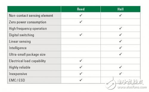
Table 1: Reed Sensor and Hall Sensor Comparison Table
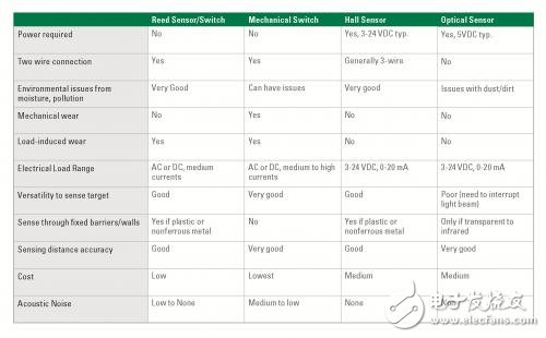
Table 2: Reed Sensors and Hall Sensors compared to other sensing technologies
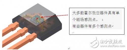
Figure 1: Hall effect sensor converts magnetic field into voltage
24HR Electronic Timer socket with photocell.
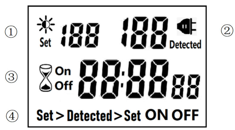
â‘ Light intensity setting
â‘¡ Light intensity detection
â‘¢ Countdown Timer ON & OFF
â‘£ 4 MODES:
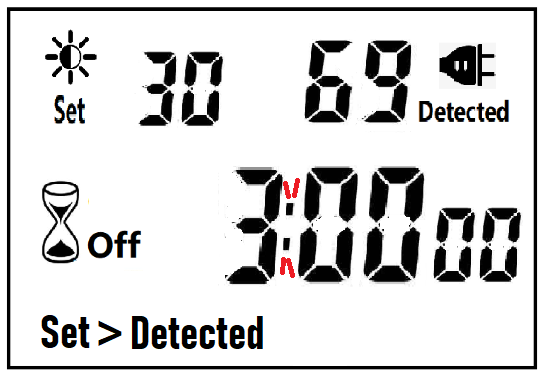
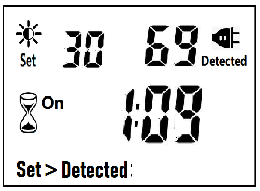
Set > Detected: When the light intensity detection value is less than the set value, switch ON or OFF.
Detected > Set: When the light intensity detection value is greater than the set value, switch ON or OFF
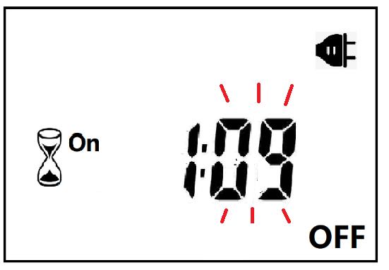
ON : Always ON
OFF : Always OFF
NOTED:
1. The light intensity displayed by this machine is not the standard light intensity value (Lux), only the relative light intensity value.
2. The light intensity value is affected by the placement position and direction. Please determine the position first and then set it according to the actual light intensity detected. If you change the position or change the orientation, you need to reset the light intensity setting value suitable for the new position.
3. This product has built-in rechargeable battery. If it is not connected to AC for a long time, you need to connect the power supply to charge until the LCD can display normally.
MANUAL OPERATION
1. Press [UP" or [DOWN" to set the LUX value.
2. Press the [SET" key to start setting, and the P1 settable items will be flashed.
3. Press [UP" or [DOWN" to adjust the value.
4. Press [SET" key again to exit setting or enter next setting for countdown timer.
5. Repeat the [SET" key to start setting, and the P2 & P3 settable items will be flashed.


6. Press the [FUN" key to switch the working state in the following:
Set > Detected -> Detected > Set -> ON -> OFF
Set > Detected: Automatically switches when the detected ambient light intensity is darker than the set value
Detected >Set: Automatically switch when the detected ambient light intensity is brighter than the set value
When the brightness meets the setting conditions, the countdown starts as below:
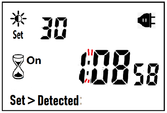
Note:when the countdown is ON, the detected value is not displayed.
When the brightness does not meet the setting conditions, the countdown stops and waits:
After the countdown ON is reduced to 0, the countdown OFF starts immediately and the power is OFF.
After the countdown OFF is reduced to 0:
A. If the light intensity meets the set conditions, a new round of countdown will be started;
B. If the light intensity does not meet the set conditions, keep the power off and wait for the light to meet the conditions before turning on automatically.
NOTE:
1. If the power is cut off while the countdown is running, the countdown will be terminated immediately and the relay output will be off. After the power is turned on again, a new round of brightness detection will start.
2. Modifying the brightness value in the countdown operation will not affect the current countdown operation. After the off time of the current countdown, the new brightness setting value will take effect.
3. In the countdown on operation, change the setting value of the countdown on, this countdown will still be timed according to the original setting value; the new setting value will take effect when the next countdown on starts.
4. In the countdown off operation, change the setting value of countdown off, this countdown will still be timed according to the original setting value; the new setting value will take effect when the next countdown off is started.
NOTE: the brightness setting value, countdown ON or countdown OFF, any one of which is equal to 0, cannot be switched ON or OFF automatically.
Manual Control
When ON or OFF is displayed, it means that the power supply remains ON or OFF, as shown in the figure below:

Power Detection and Standby Mode
With AC power supply, the icon ![]() lights up and works normally.
lights up and works normally.
When there is no AC power supply, the icon ![]() goes out, the brightness is not detected at this time, and the system enters the standby mode.
goes out, the brightness is not detected at this time, and the system enters the standby mode.
Photocell Timer, photocell timer socket, photocell sensor, photocell sensor socket, sensor plug, sensor switch socket, digital photocell timer, digital sensor timer
NINGBO COWELL ELECTRONICS & TECHNOLOGY CO., LTD , https://www.cowellsocket.com