The CAN bus load ratio is only a macroscopic parameter, and it cannot fully evaluate the effectiveness and scalability of the bus. The definition of the load ratio in the industry is the ratio of the actual data transmission rate and the data transmission rate that can theoretically be achieved. This paper mainly describes how the CAN bus load ratio can be calculated and the CAN bus load rate must be less than 30%. Follow Xiaobian to find out.
CAN bus load rate must be less than 30%The CAN bus load rate does not have to be less than 30%, because in 12 years Fiat can still guarantee normal communication at a load rate of 70%, so this 30% is just the best choice.
The higher the load rate is, the more data is needed to be sent, and the more likely the communication delay of the lower priority node is.
According to the experiment, under the condition of 30% load factor, the average packet transmission time of the high-priority node is almost the same as the theoretical transmission time; while the low-priority one has the delay of about 20%; when the load rate reaches 60% Under the circumstances, the node with the highest priority has a delay of at least 25%, the delay with the lowest priority reaches 4 times, and it cannot meet the real-time performance at all; when the average bus utilization rate exceeds 70%, the communication of the bus will be With the possibility of congestion, extreme situations can cause the appearance of error frames.
Therefore, the lower the load rate is, the better, and the more real-time performance is ensured. However, if the load ratio is too low, enough data cannot be transmitted. This is a problem of CAN. When the data volume is large, real-time performance cannot be guaranteed. The general statement is that about 30% of the load rate is the best.
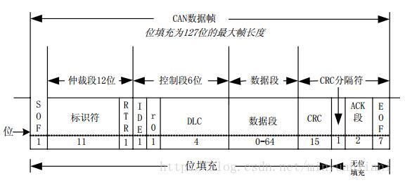
CAN bus load principle and calculationA. CAN standard frame format
B.CAN extended frame format

C. Interframe spacing

Hypothesis
Ui: The percentage of occupied buses for each message frame
L: the total length of the packet
C: bus occupancy time for the message
N: the number of bits to fill
t: the bit time for the hair rate (also known as baud rate)
Then there are:
L = N + 8d + g + 13
C = L * t
Ui = C / T
However, the bus load ratio is the sum of the bus percentages occupied by each information frame.
U = U1 + U2 + U3 + . . . . .
g is the total number of control bits in the CAN message (standard frame g = 34, extended frame g = 54)
The value of g is to take only the bit filling part to remove the data segment;
13: No bit padding + interframe space
Network load rate algorithm example:

The network load ratio is the percentage of the bandwidth occupied by the network bus data within 1 s. Taking the above network matrix table as an example, assuming that the bus speed is 500 Kbps, there are multiple frames of signals in the network, the load rate occupied by each signal frame is calculated, and the total network load ratio is obtained by addition. The FBCM_1 / FBCM_2 two frames of the load rate algorithm is as follows:
Load rate 1 = (1000ms / 20ms) * 111 / 500000 = 0.0111 = 1.11%
Load rate 2 = (1000ms / 10ms) * 111 / 500000 = 0.0222 = 2.22%
The formula 111 is an 8-byte data frame with no padding bits.
111 = 34 + 13 + (8 byte X 8bit) = 47 + 64
Here we see such a formula in TTCAN:

According to the CAN protocol, the same level lasts 5 bits, and the next bit is inserted at the level of the 1st bit and the 5th bit inversion.
It can be seen that: (34 + 8s)/5 gets the number of padding bits, so for a complete number of bits in a frame, we can assume that we have an upper interval bit.
Then: Padding: (34 + 8s)/5
Data bit: 8s
Message format bits: 34 + 10 + 3 = 47
A separate slip ring is a device that allows two or more rotating electrical shafts to be connected without having to pass the electricity through the shafts' bearings. This is often used in situations where there is a need to power something externally while the shaft is still turning. For example, a machine might have a drive shaft that powers it while also having a separate output shaft that needs to turn at a different speed. By using a separate slip ring, these two shafts can be powered without any interference.
Slip Ring Shaf is a key component of a slip ring. It is the shaft on which the rotary electrical contacts are mounted. The shafts must be strong enough to support the weight of the contacts and must be able to turn freely. There are many factors to consider when selecting a shaft material, including strength, corrosion resistance, and operating temperature.
Oubaibo is a professional separate slip ring manufacturer located in China. They offer a wide range of slip ring shaft made from different materials, including carbon steel, stainless steel, and brass. Their products are made to meet the highest quality standards and are backed by a 100% satisfaction guarantee.
Separate Slip Ring,Slip Ring Shaft,Slip Ring 4 Wire,Slip Ring For Motor
Dongguan Oubaibo Technology Co., Ltd. , https://www.sliprob.com