Is it possible to use no auxiliary coil?
â— If the auxiliary coil is not required for power supply, can it be used for primary feedback with other detection methods, such as detection on the primary coil?
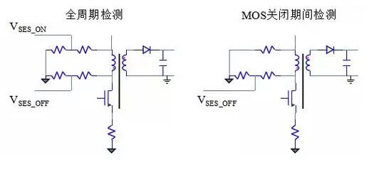
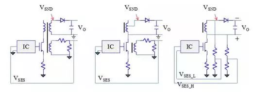
â— Theoretically feasible, the idea is as follows: - Connect a high-impedance branch in parallel with the primary coil, sample the primary coil, and provide the primary coil loop during TOFF. - Considering that the detection voltage must be positive, there are two basic forms, as shown below:
How to check output information
â— The primary feedback cannot get all the output information, but more output information can be obtained. - The output current information cannot be obtained, but the primary current information can be obtained. - The output voltage information cannot be obtained directly, and the output voltage information can be obtained through the auxiliary winding.
Detectability
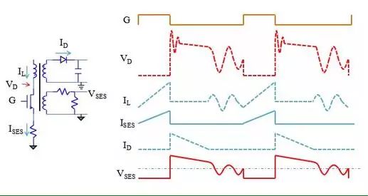
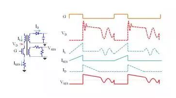
â— The voltage across the inductor is too high, it is difficult to detect IL and VD, detected by ISES and VSES;
â— Considering the isolation requirements, the secondary current and output voltage cannot be directly detected and can only be calculated from other values.
PSR output voltage calculation
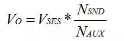
â— After the MOS tube is turned off, the energy stored in the transformer is released from the secondary and auxiliary coils. The secondary coil and the auxiliary coil form a transformer. The voltage on the VSES is:
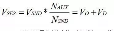
â— VD is related to the current of the secondary coil. The smaller the current is, the smaller the VD is. When the current is 0, VD is 0. â— Therefore, at the demagnetization point, the VO voltage is:
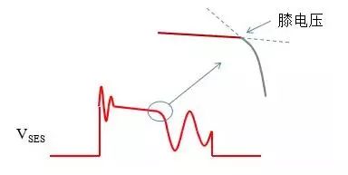
Definition of knee voltage
â— When the current flowing through the secondary diode is 0, the transformer is demagnetized. At this time, VD is higher than VIN by a reflected voltage. The LC circuit formed by the primary inductance and parasitic capacitance starts to oscillate, and the voltage on the primary inductor starts from VD-VIN. Falling sinusoidally.
â— In this way, the voltage seen on the VSES will appear as a knee, so the voltage of the demagnetization point is called the knee voltage. Because the slope at the sinusoidal starting point is -1, the knee voltage is the voltage at which the slope of the voltage changes from when the slope of the load consumption changes to -1.
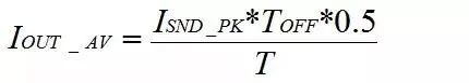
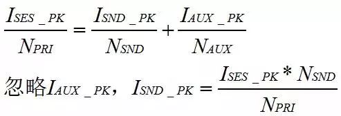
PSR output current calculation â— After the MOS transistor is turned off, the energy stored in the transformer is released from the secondary and auxiliary coils. The average secondary current is:
â— ISND_PK cannot be measured directly. It can only be converted by ISES_PK:
â— The measurement of TOFF also depends on the moment of the knee voltage, but it is not the voltage value but the time of the knee point.
The common point of current and voltage detection
â— The common point is that all knee points need to be detected.
â— For the current, the knee point is detected, and then the TOFF is calculated based on the knee point and the moment when the switch is opened. The average output current can be calculated by adding the current of the ISES.
â— For the voltage, the voltage of the knee point needs to be detected. The specific method is to detect the knee point and then look at the voltage at the current time VSES so as to obtain the output voltage at the current moment according to the turns ratio.
Knee point detection algorithm
â— There are two kinds of detection methods, one is to go back and forth, and the other is to go back and forth. - Detect from the back and forth is to find the moment of the knee by delaying or changing the slope. - Detection from the back to the front uses the feature that the resonance frequency is fixed after the knee point, and pushes the knee point from the zero crossing point.
Comparison of methods
â— Delay method, starting from TOFF, delaying for a period of time and detecting VSES. - This method is conceivably very inaccurate because the time of TOFF varies greatly.
â— Detect the slope method, detect the slope of VSES, and find the knee point by the waveform analysis algorithm. - This method works only when there is a significant difference between the slope of the TOFF interval and the slope of the TDEAD interval, and since the oscillation is sinusoidal in the TDEAD interval, there is no slope transition at the knee point and an algorithm must be used to calculate the knee point.
â—Resonance backstepping method. After the knee point, the resonance of the primary inductance is transmitted to the auxiliary coil. The resonance frequency can be known by detecting the zero-crossing point of the auxiliary coil. When the zero crossing point is used, the 1/4 cycle is subtracted, which is the knee point. - This method is used to measure the time constant current is relatively simple, when used for constant voltage must be the voltage detection into time detection.
Resonance backstepping method to achieve constant pressure
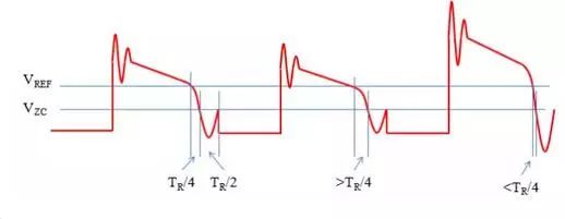
â— After resonance, detecting the zero-crossing point of the secondary coil can tell the resonance period. Therefore, when the output voltage is exactly equal to the reference voltage, the time from the intersection of VSES and VREF to the zero-crossing point should be exactly equal to 1/4 resonance period TR. . If TFB is greater than TR/4, the output voltage is low, so that the intersection of VSES and VREF advances. Conversely, if TFB is smaller than TR/4, the output voltage is higher, so that the intersection of VSES and VREF is delayed. -VZC is zero crossing threshold, not 0V, usually a very small voltage, such as 0.125V
Comparison of slope method and resonant backstepping method
• It is noted that the slope method and the resonant backstepping method are complementary in their advantages and disadvantages: - If the slope difference during TOFF and TDEAD is greater, the slope method is more appropriate. If the slope difference between TOFF and TDEAD is smaller, the more suitable the resonance is, Push method. - Actually, the slope during TOFF is usually so small that noise has a great influence on the detection of VSES and VREF crosspoints. If a resonant backstepping method is used, there must be some way to eliminate noise.
◠It is also necessary to pay attention to the use of resonant backstepping method. Due to the large difference between the slope before and after the knee point and the large and small TFB, the error time TERR=TR/4 – TFB has completely different loops when it is greater than 0 and less than zero. Gain. - The lower the slope, the greater the time difference between output voltage variations and the higher the loop gain. That is, when the output voltage is less than the reference voltage, the loop gain is high. When the output voltage is greater than the reference voltage, the loop gain is increased. low.
Use PSR technology for non-isolated topology
â— Generally speaking, a non-isolated topology can directly detect the output VO. There is no need to use complex PSR technology to detect VSND first and then calculate VO, with the exception of the requirement that one IC support both isolation and non-isolation. - From a market perspective, isolation and non-isolation are all needed. If the same technology is used to solve, it will undoubtedly save a lot of research and development costs.
Problems inherent in PSR
â— Non-real-time detection: Only one opportunity to correctly detect the output voltage in each switching cycle can not be detected anytime and anywhere like other non-isolated topology, and the detection of this output voltage also depends on the demagnetization of the transformer. Before the demagnetization point has arrived, any changes at the output cannot be detected.
â— Cable voltage drop: It can be obtained that the voltage is only the voltage across the capacitor, not the voltage across the load. When the secondary has obvious parasitic resistance, the detected voltage will be significantly lower. - At the demagnetization point, the current flowing through the diode is 0, the voltage across the capacitor is equal to the voltage at the secondary, but the current through the parasitic resistance is not zero, and the voltage on the load is less than the detected voltage.
The problem of load mutation
â— Non-real-time detection is mainly reflected in sudden load changes, such as hot-swapping. - In the field of chargers, hot plugging must be supported. In the LED field, hot plugging is also necessary to support, and many specifications require hot plugging. - Hot plugs include the extreme conditions of no load -> full load, and full load -> no load. - In the real world, not every time it is fully loaded, but if it can support full-load switching, it is bound to support other switching.
â— An empty->full handoff will cause the output to drop, and a full-to-empty handoff will cause an output overshoot. To avoid these two conditions, a non-linear control must be used. The IC immediately adjusts the control strategy after detecting a hot swap.
Hot drawing
â— If in the TOFF interval, that is, when the secondary output is hot-swapped, which corresponds to a sudden increase in the secondary load impedance, there will be a small sudden change in voltage, and then all the energy will be accumulated on the capacitor and the output voltage will rise. high.
â— If you hot-swap in a non-TOFF interval, except that you cannot see a small voltage change, the final result is the same as the previous one.
Dummy load
â— If it is not guaranteed that every time it can be detected and the hot-drawing can be handled, a dummy load or a voltage regulator must be added to the output so that it can take over the discharge. - The dummy load generally uses resistance, and the resistance value must be carefully selected. If the discharge is too large, the discharge effect is not good. If the load is too small, the power consumption is too low.
Hot insertion and short circuit judgment
â— During hot plugging, the load suddenly becomes smaller, the output voltage will drop, and the power supply needs to output more energy to the secondary, but to distinguish between hot plugging and shorting.
â— It is not only necessary to distinguish between hot plugging and short-circuiting. It is necessary to judge whether or not the short circuit occurs at any time. - When the short-circuit occurs, the TOFF time will be very short. It can be judged by checking the time from the start of TOFF to the VSES zero-crossing point, or by the slope of the TOFF interval. - If the output is not short-circuited during TOFF, it will wait until the next TOFF to detect it. After the short-circuit, the output capacitor will have a large current. If this long-time current is too long, the temperature of the capacitor will rise and the capacitor will increase in temperature. Life will have a certain influence, so it is important to detect TOFF as early as possible. - Assuming that it takes one or two cycles to detect a short circuit, it will not affect the lifetime of the capacitor. This is unclear. Differentiate hot plug, short circuit, boot
â— All three of them show that the output needs to absorb a lot of energy, but the three methods cannot be the same. - Hot-plugging requires voltage regulation to reduce the magnitude and duration of the drop, short-circuits need to be identified, and protection measures are taken, whereas starting up requires a controlled increase in output.
â— The main differences between these three are: - The initial state is different, the initial state of hot plugging is unloaded, the initial state of the short circuit is arbitrary, and the initial state of the boot is the initial state. - The effect on the output is different. Since the initial state output of the boot is 0, the output after the boot is increased, and the other two are reduced, so the distinction between hot-insertion and short-circuit is more difficult.
Hot swapping jitter
â— In the process of human plugging and unplugging, the terminals are actually shaking and they will perform a quick collision. That is, there will be a lot of switching during plugging and unplugging.
â— If the IC's detection control is handled improperly, it is likely to cause problems. The reason for the problem is that the switching frequency has dropped to a very low level at no-load, and the switching frequency is usually high at full load, and the chip cannot switch quickly between these two conditions.
Back Seat Headrest Pillow Phone Holder
Back Seat Headrest Pillow Phone Holder,Samsung Tablet Car Holder Back Seat,Car Back Seat Organiser With Tablets,Car Back Seat Tablet Holder
Ningbo Luke Automotive Supplies Ltd. , https://www.nbluke.com