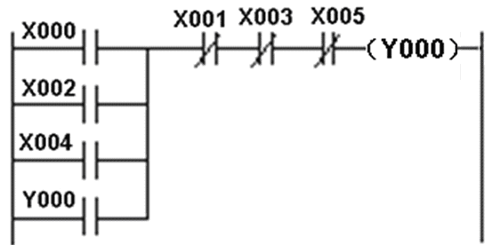
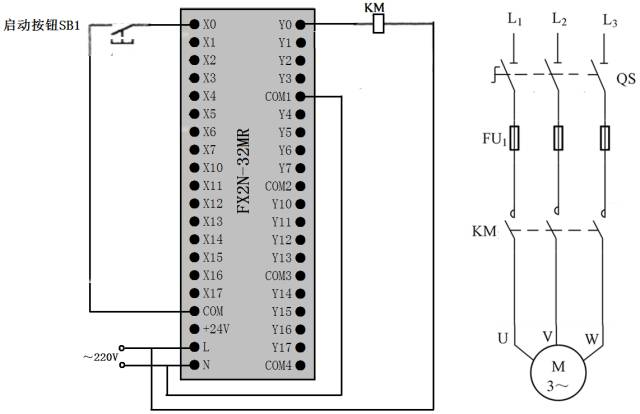
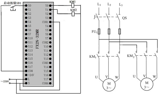
PLC circuit and ladder diagram for start, self-lock and stop control
Starting, self-locking, and stopping control can be implemented using drive commands (OUT) or set commands (SET, RST).
1. Start, self-lock and stop control using coil drive instructions

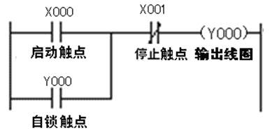
The line and ladder diagrams are as follows:
When the start button SB1 is pressed, the start contact X000 in the ladder program inside the PLC is closed, the output coil Y000 is energized, the internal hard contact of the output terminal Y0 is closed, the internal connection between the Y0 terminal and the COM terminal, and the contactor coil KM got electricity, the main circuit in the KM main contact is closed, the electric motor was started.
When the stop button SB2 is pressed, the stop contact X001 in the ladder program inside the PLC is turned off, the output coil Y000 is de-energized, the internal hard contact between the Y0 and COM terminals is disconnected, and the contactor coil KM is de-energized. The KM main contacts in the circuit are disconnected, and the motor stops in a de-energized state.
2. Use set reset instruction to start, self-lock and stop control
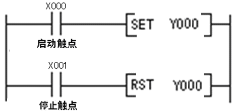
The PLC wiring diagram is the same as above.
The line and ladder diagrams are as follows:
When the start button SB1 is pressed, the start contact X000 in the ladder diagram is closed and the [SET Y000] command is executed. The command execution result sets the output relay coil Y000 to 1, which is equivalent to the power of the coil Y000, so that the Y0 and COM terminals are between The internal hard contact is turned on, the contactor coil KM is energized, the KM main contact in the main circuit is closed, and the motor is started electrically.
When the stop button SB2 is pressed, the stop contact X001 in the ladder program closes and the [RST Y000] command is executed. The command execution result resets the output coil Y000, which is equivalent to the loss of power to the coil Y000 and between the Y0 and COM terminals. The internal hard contact is disconnected, the contactor coil KM is de-energized, the KM main contact in the main circuit is disconnected, and the motor is de-energized and stopped.
PLC line and ladder diagram of positive and reverse interlock control

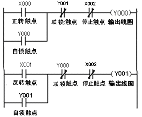
The line and ladder diagrams are as follows:
1) Forward rotation interlock control. Press the Forward Button SB1 → The Forward Contact X000 in the Ladder Program Closes → The Ring Y000 Receives Power → The Y000 Lock Contact Closes, the Y000 Interlock Contact Opens, and the Internal Hard Contact Between the Y0 Terminal and the COM Terminal Closed → Y000 self-locking contact closed, so that the coil Y000 can still get electricity after the X000 contact is disconnected; Y000 interlocking contact is open, so that the coil Y001 cannot be closed even when the X001 contact is closed (caused by SB2 operation) Get power and realize interlock control; the internal hard contact between Y0 terminal and COM terminal is closed, the contactor KM1 coil is energized, the main contact of KM1 in the main circuit is closed, and the electric motor has positive rotation.
2) Reverse interlock control. Press the invert button SB2 → reverse contact X001 in the ladder program → coil Y001 electrify → Y001 latch contact closed, Y001 interlock contact open, internal hard contact between Y1 terminal and COM terminal Closed → Y001 latching contact is closed, the coil Y001 continues to be energized after the X001 contact is opened; Y001 interlocking contact is opened, so that the coil Y000 cannot be obtained even when the X000 contact is closed (incorrectly caused by SB1) Electricity, to achieve interlock control; internal hard contact between the Y1 terminal and the COM terminal is closed, the coil of the contactor KM2 is energized, the KM2 main contact in the main circuit is closed, and the electric motor is reversed.
3) Stop control. Press the stop button SB3 → The two stop contacts X002 in the ladder program are disconnected → The coils Y000, Y001 are all de-energized → The coils of the contactors KM1, KM2 are all de-energized → The main contacts of the KM1, KM2 in the main circuit are Disconnect, the motor stalled.
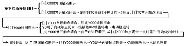
Multi-control PLC circuit and ladder diagram
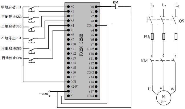
(1) Single and multiple control
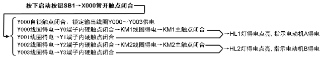
A start control. When the start button SB1 is pressed on the ground → → X000 normally open contact closes → coil Y000 electrified → Y000 normally open self-locking contact is closed, Y0 terminal internal hard contact is closed → Y000 normally open self-locking contact closes lock Y000 coil Power supply, the internal hard contact of Y0 terminal is closed, the contactor coil KM is powered → the main KM main contact in the main circuit is closed, and the motor is powered.
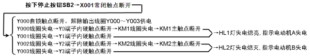
A to stop the control. When the stop button SB2 is pressed on the ground → → the normally closed contact of X001 is opened → the power failure of the coil Y000 → the normally open self-locking contact of Y000 is opened, the internal hard contact of the Y0 terminal is disconnected → the contactor coil KM is de-energized → main The KM main contacts in the circuit are disconnected, and the motor stops in a de-energized state.
(2) Multi-person control
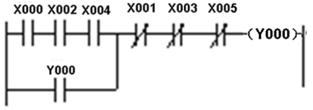
Start control. Press button SB1, SB3, SB5 → coil Y000 at the same time in A, B and C at the same time → Y000 normally open self-locking contact is closed, internal hard contact of Y0 terminal is closed → Y000 coil power supply locks, contactor coil KM In the main circuit, the main contact of the KM is closed and the motor is powered.
Stop the control. When one of the stop buttons SB2, SB4, or SB6 is pressed in A, B, or C three places → The coil Y000 is de-energized → The Y000 normally open self-locking contact is opened, and the Y0 terminal internal hard contact is opened → Y000 is normally open The disconnection of the self-locking contact causes the Y000 coil to be powered off, the internal hard contact of the Y0 terminal is disconnected, the contactor coil KM is de-energized, the KM main contact in the main circuit is disconnected, and the motor is de-energized and stopped.
Timing controlled PLC circuit and ladder diagram
1. PLC circuit and ladder diagram of delayed start timing operation control
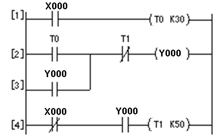
The function that it can realize is: After pressing the start button for 3 seconds, the motor starts to run and stops automatically after 5 seconds of running.
The PLC circuit and ladder diagram are described as follows:
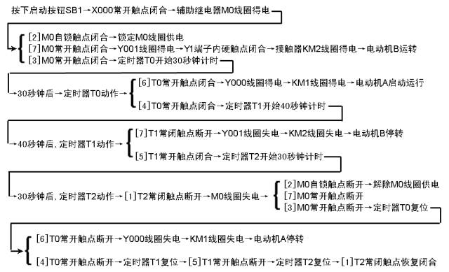
2. PLC line and ladder diagram with multiple timer combination control
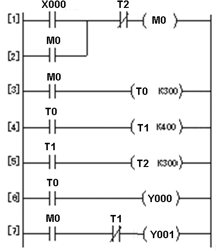
The functions that can be realized are: After the start button is pressed, the motor B runs immediately. After 30 seconds, the motor A starts to run. After 70 seconds, the motor B stops, and after 100 seconds, the motor A stops.
The PLC circuit and ladder diagram are described as follows:
Combination of Timer and Counter to Extend Timing Control PLC Circuit and Ladder Diagram
Mitsubishi FX series PLC's maximum timing is 3276.7s (approximately 54min). Timers and counters can be used to extend the timing.
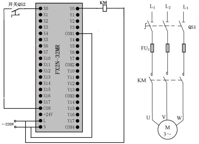
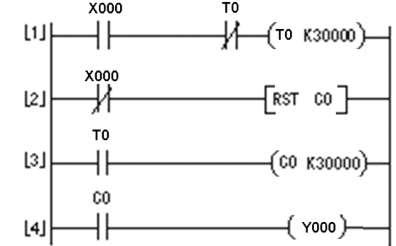
The PLC circuit and ladder diagram are described as follows:
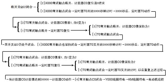
The timing unit of the timer T0 in the figure is 0.1 s (100 ms). When it is used in combination with the counter C0, the timing T is 30000×0.1 seconds×30000=90000000 seconds=25000 hours. If re-timing is needed, switch QS2 can be opened and the [2]X000 normally closed contact can be closed, and the “RST C0†instruction can be executed. If the counter C0 is reset, then QS2 is closed again, the 250,000-hour timing restarts.
Multi-output control PLC circuit and ladder diagram
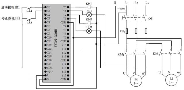

The PLC circuit and ladder diagram are described as follows:
(1) Start control
(2) stop the control
PLC circuit and ladder diagram for overload alarm control


The PLC circuit and ladder diagram are described as follows:
(1) Start control
Press the start button SB1 → [1] X001 contact closes normally → [SET Y001] command execution → Y001 coil is set, ie Y001 coil is energized → internal hard contact of Y1 terminal is closed → contactor KM coil is energized → The KM main contact is closed → the motor is powered.
(2) stop the control
Press the stop button SB2 → [2] X002 Normally open contact closed → [RST Y001] command execution → Y001 coil is reset, ie Y001 coil is de-energized → internal hard contact of Y1 terminal is disconnected → contactor KM coil is de-energized → The KM main contact is open → the motor is de-energized and stopped.
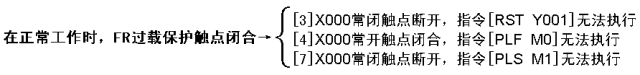
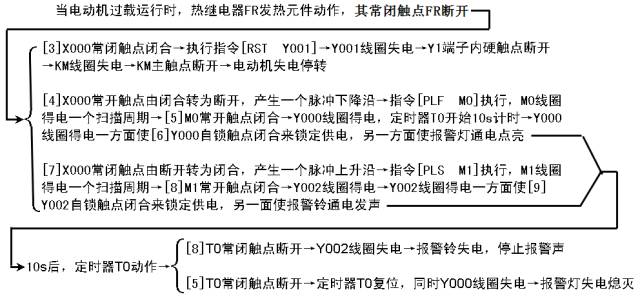
(3) Overload protection and alarm control
Flashing Controlled PLC Line and Ladder Diagram
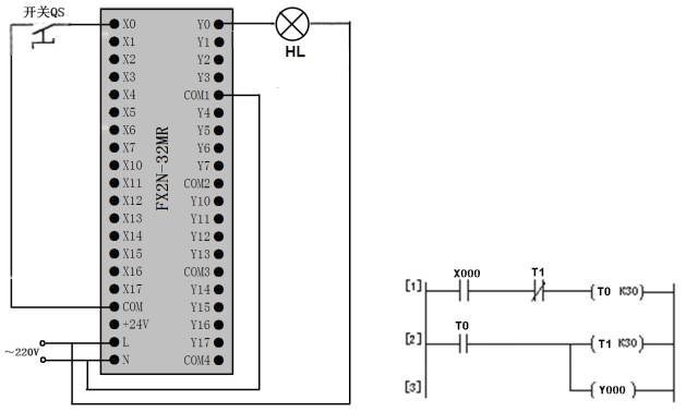
The line and ladder diagrams are as follows:
Switch QS closed → X000 normally open contact closed → Timer T0 start 3s time → 3s, timer T0 action, T0 normally open contact closed → timer T1 start 3s time, while Y000 get electricity, Y0 terminal internal hard When the contact is closed and the lamp HL is lit → 3s, the timer T1 activates, the T1 normally closed contact opens, the timer T0 resets, the T0 normally open contact opens, the Y000 coil de-energizes, and the timer T1 resets → Y000 The coil is de-energized and the lamp HL is extinguished; the timer T1 resets and T1 closes. Since the switch QS is still closed, the X000 normally open contact is also closed, and the timer T0 restarts the 3s time again.
After repeating the above process, the lamp HL keeps flashing at the frequency of 3s bright and 3s off.
Exercise
1. Fountain's PLC control
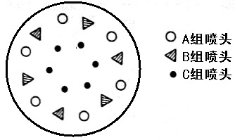
The system requires two buttons to control A, B, and C groups of nozzles (by controlling the motors of the three groups of nozzles). The arrangement of the three nozzles is shown in Figure 4-32. The system control requirements are as follows:
When the start button is pressed, group A nozzles stop after spraying for 5 seconds, then group B and group C spray at the same time. After 5 seconds, group B nozzles stop, group C nozzles continue to spray for 5 seconds and then stop, then group A and group B spray nozzles for 7 seconds. The nozzles of group C were stopped within the first 2 seconds of the 7 seconds, and the water was sprayed within 5 seconds. Then, the three groups of nozzles A, B, and C were simultaneously stopped for 3 seconds, and the foregoing process was repeated thereafter. After pressing the stop button, the three nozzles stop spraying at the same time.
2. PLC control of traffic lights
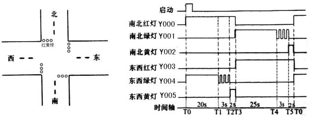
The system requires two buttons to control the traffic lights. The traffic lights are arranged as shown in Figure 4-36. The system control requirements are as follows:
When the start button is pressed, the north and south red lights are on for 25s. In the time when the north and south red lights are on for 25s, the green light is first lit for 20s and then flashed 3 times with a frequency of 1/s. Then the yellow light is on for 2s, and after 25s, the north and south are red. The light goes out and the extinguishment time is maintained for 30 seconds. In this 30s time, the red light is always high, the north-south green light is on for 25 seconds, then it flashes 3 times with a frequency of 1/s, and the yellow light on the north and south lights up for 2 seconds. Repeat this process later. After pressing the stop button, all lights are off.
7.5 Mm Nano Tip,Smart Pen Infrared,Infrared Pen Touch,Slim Infrared Pen
Shenzhen Ruidian Technology CO., Ltd , https://www.szwisonen.com