1. Problem Statement
Application Overview
The design of motor control systems is a multi-disciplinary issue, including mechanical, electrical and control systems. OPTIMUS can explore the design space and automatically improve the design without user intervention through its powerful optimization algorithm. This application case demonstrates how OPTIMUS is integrated with Simulink, by modifying (a) the magnetic pole width of the motor (b) the excitation signal, to optimize the output torque ripple and switching loss of the motor.
Design problem
The control system model is established in Simulink. The electromagnetic fields corresponding to the different pole widths of the motor have been calculated in ANSYS, and the coil inductance is imported into the Simulink model as a result. The inverter circuit is modeled in PSpice, and then the circuit module is converted into a module compatible with Simulink through the SLPS interface, thereby completing the integration.
Software tools used
• OPTIMUS and its Matlab / Simulink interface • Simulink
• PSpice (SLPS interface)
• ANSYS
Simulation process and OPTIMUS workflow OPTIMUS graphical user interface integrates simulation programs, their workflow and input and output files. Through the interface between OPTIMUS and Matlab / Simulink, OPTIMUS conveniently parameterizes the simulation input file and parses out the required output parameters from the output file (Figure 1).
model
The motor in the case is a 3-phase excited, 6-pole stator, 4-pole rotor switched reluctance motor (SRM). The control system simulation is established in Simulink, the electromagnetic field of the motor is calculated in ANSYS, and the inverter circuit is modeled in PSpice. (figure 2)
The three design parameters are the motor pole width, the starting angle of the excitation signal and the width of the excitation signal. The optimization goal is to minimize the ripple of the motor output torque. The constraint is that the motor speed is greater than 1000 RPM.
Method application
Experimental design and response surface model
Design of Experiments (DOE) method and Response Surface Model (RSM) are used to explore the design space. In this case, the Latin hypercube method of 100 sample points is applied. On this basis, a least squares response surface based on Taylor polynomial was established to fit the sample points of the experimental design.
Design Optimization
In this case, OPTIMUS applied adaptive evolution (SAE) genetic algorithm to find the minimum motor output torque ripple by solving on the response surface, while also satisfying that the motor speed is not less than 1000 RPM. The optimal solution found on the response surface is used as the starting point in the local optimization process of the simulation workflow solution. In this way, through the strategic combination of several optimization algorithms and different solving methods, it is finally possible to find the global optimal design, and at the same time shorten the time of the optimization process.
Explanation of results
Experimental design and response surface model
The Latin hypercube test design method was run to establish the sample of the corresponding surface. Figure 4 shows that the motor pole width and excitation signal width are important design parameters that have a greater impact on output torque ripple. This response surface model is an approximation of the simulation model. In the optimization process, if you need to continuously solve a large number of simulation models, it will require a considerable amount of calculation. Appropriate use of response surface model can effectively reduce the amount of calculation and improve the efficiency of the optimization process. The quality of the response surface model (and its reliability for the optimization process) can be confirmed by the regression coefficients obtained during the establishment process.
in conclusion
OPTIMUS successfully automated the Simulink simulation and found the optimal magnetic pole width, starting angle and width of the excitation signal, which effectively reduced the output torque ripple of the motor and ensured that the motor speed was always higher than the specified speed.
income
• Automate existing simulation processes • Free engineers from repetitive labor • Design space exploration and powerful optimization methods help find optimal designs and meet constraints.
Application Overview
The design of motor control systems is a multi-disciplinary issue, including mechanical, electrical and control systems. OPTIMUS can explore the design space and automatically improve the design without user intervention through its powerful optimization algorithm. This application case demonstrates how OPTIMUS is integrated with Simulink, by modifying (a) the magnetic pole width of the motor (b) the excitation signal, to optimize the output torque ripple and switching loss of the motor.
Design problem
The control system model is established in Simulink. The electromagnetic fields corresponding to the different pole widths of the motor have been calculated in ANSYS, and the coil inductance is imported into the Simulink model as a result. The inverter circuit is modeled in PSpice, and then the circuit module is converted into a module compatible with Simulink through the SLPS interface, thereby completing the integration.
Software tools used
• OPTIMUS and its Matlab / Simulink interface • Simulink
• PSpice (SLPS interface)
• ANSYS
Simulation process and OPTIMUS workflow OPTIMUS graphical user interface integrates simulation programs, their workflow and input and output files. Through the interface between OPTIMUS and Matlab / Simulink, OPTIMUS conveniently parameterizes the simulation input file and parses out the required output parameters from the output file (Figure 1).
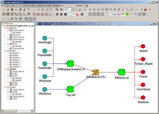
Figure 1-OPTIMUS workflow for motor control system simulation
model
The motor in the case is a 3-phase excited, 6-pole stator, 4-pole rotor switched reluctance motor (SRM). The control system simulation is established in Simulink, the electromagnetic field of the motor is calculated in ANSYS, and the inverter circuit is modeled in PSpice. (figure 2)
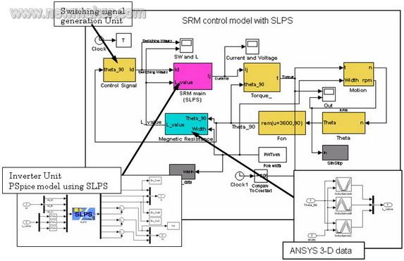
Figure 2-Simulink model of the motor control system
The three design parameters are the motor pole width, the starting angle of the excitation signal and the width of the excitation signal. The optimization goal is to minimize the ripple of the motor output torque. The constraint is that the motor speed is greater than 1000 RPM.
Method application
Experimental design and response surface model
Design of Experiments (DOE) method and Response Surface Model (RSM) are used to explore the design space. In this case, the Latin hypercube method of 100 sample points is applied. On this basis, a least squares response surface based on Taylor polynomial was established to fit the sample points of the experimental design.
Design Optimization
In this case, OPTIMUS applied adaptive evolution (SAE) genetic algorithm to find the minimum motor output torque ripple by solving on the response surface, while also satisfying that the motor speed is not less than 1000 RPM. The optimal solution found on the response surface is used as the starting point in the local optimization process of the simulation workflow solution. In this way, through the strategic combination of several optimization algorithms and different solving methods, it is finally possible to find the global optimal design, and at the same time shorten the time of the optimization process.
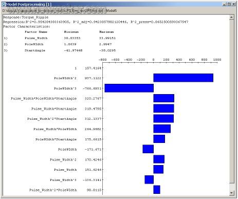
Figure 3-The contribution graph shows that the motor pole width and the initial angle of the excitation signal are the design parameters that have the greatest impact on the output torque ripple
Explanation of results
Experimental design and response surface model
The Latin hypercube test design method was run to establish the sample of the corresponding surface. Figure 4 shows that the motor pole width and excitation signal width are important design parameters that have a greater impact on output torque ripple. This response surface model is an approximation of the simulation model. In the optimization process, if you need to continuously solve a large number of simulation models, it will require a considerable amount of calculation. Appropriate use of response surface model can effectively reduce the amount of calculation and improve the efficiency of the optimization process. The quality of the response surface model (and its reliability for the optimization process) can be confirmed by the regression coefficients obtained during the establishment process.
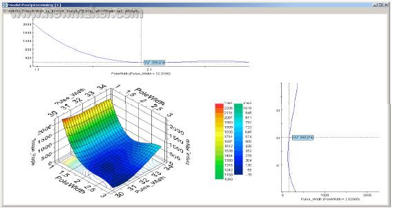
Figure 4-OPTIMUS setup response surface showing the relationship between output torque ripple and selected input parameters
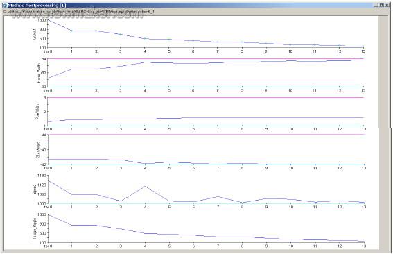
Figure 5-Optimizing the convergence of the objective function: Minimizing the output torque ripple
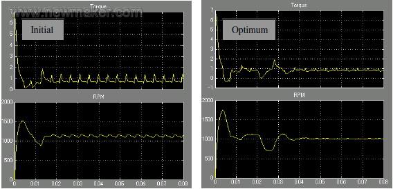
Figure 6-Motor output torque and speed before and after optimization
in conclusion
OPTIMUS successfully automated the Simulink simulation and found the optimal magnetic pole width, starting angle and width of the excitation signal, which effectively reduced the output torque ripple of the motor and ensured that the motor speed was always higher than the specified speed.
income
• Automate existing simulation processes • Free engineers from repetitive labor • Design space exploration and powerful optimization methods help find optimal designs and meet constraints.
Yiwu YiTong Trading company , https://www.nx-vapes.com