Free-form surface optics is a change in the lighting industry's ability to redirect light to a target area. Non-uniform rational B-splines, commonly referred to as NURBS, are widely used to represent free-form surfaces and surfaces. There are some optical systems that require local modification of the surface during the design or optimization phase. In this case, NURBS cannot provide this conversion. But a new mathematical expression called T-splines makes this possible. Although its potential has been well described, it has not been implemented in any optimization procedures so far. Annie Shalom Isaac, Jiayi Long and Cornelius Neumann from the Karlsruhe Institute of Technology demonstrated the advantages of local refinement capabilities by performing T-splines in the optimization program and evaluated the results. The results show that the T-spline provides a more uniform and uniform light distribution and a faster convergence rate than NURBS. This makes optical design or optimization using T-splines an intuitive method for future free-form design tasks.
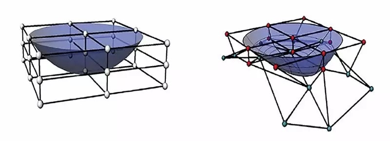
3x3 OFFD grids are closed and optical surfaces before (left) and (right) deformation
The design of free-form optics relies heavily on one of the following methods: based on point source assumptions [3], SMS design [4] and cropping of source target maps based on equal flux grids [5] to create an initial Optical surface. Because these mathematical methods do not guarantee accurate results for extended LED sources and do not provide a versatile solution, optical designers still rely on any optimization tool to improve results. The speed improvement in the ray tracing algorithm and the complex intelligent optimization algorithm make the application of the optimization method more extensive. However, the shortcomings of free-form surface optimization are mainly due to its complex mathematical expression and the existence of many parameters.
Wendel et. Al proposed a method called optimization, using free deformation (OFFD) to overcome this difficulty, placing the optical surface in the mesh and deforming the closed mesh instead of acting directly on the mesh [1]. This method uses NURBS to represent optical surfaces, and the results show that with less optimization variables, they can achieve global deformation well, which makes manufacturing easier. However, in some cases there is a significant tilt in the light distribution, or the path of the light must change significantly. In this case, a slight local deformation will bring about a significant improvement. But for the current OFFD, this is not possible because the surface is represented below. Another surface representation called T-spline can overcome this shortcoming [2]. Bailey et al. Al has demonstrated the potential of T-splines and its application to optical surfaces [6]. But so far, this method has not been applied to any optimization procedures, nor has its optical performance been analyzed and compared with NURBS.
Therefore, this work takes this issue into consideration and provides an alternative to solving this problem. Part 2 introduces the OFFD technology. The mathematical surface representation of the optical surface is described in Section 3. The results of the T-spline and the results of the comparison are shown in Section 4, followed by a conclusion in Section 5.
Optimize with OFFD
The OFFD method uses the free-form deformation (FFD) technique proposed by Sederberg [7] and incorporates an optimization program. The relationship between the mesh and the optical surface is well established using the FFD algorithm [7]. Figure 1 shows a grid with optical surfaces before and after deformation. For the sake of brevity, only an overview of the OFFD method will be introduced.

A 3x3 OFFD mesh envelop and optical surface (left) and back (right) deformation
The algorithm first selects an input surface whose optical performance must be improved, which is usually far from the target. In this way, the optical surface is enclosed within a grid of 27 grid control points, and the user can select any combination from them. This is provided as a variable to the optimization algorithm. The optimization algorithm has a wide search space for selected grid point combinations and provides movement along a three-dimensional closed grid. As the closed mesh changes, it also changes its internal optical surface. The deformed surface is then photometrically evaluated, and the optimization algorithm determines the variation of its optimized variables based on this result. The algorithm is repeated over and over until the target lighting requirements are met.
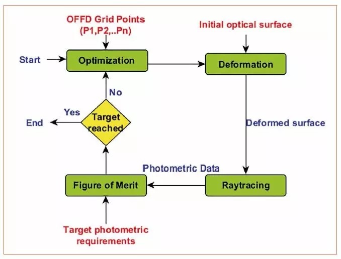
Free deformation optimized workflow (OFFD)
The most important step in this program is the definition of the quality factor of the deformed optical surface, since the entire optimization is based on this single value, called Q. In this article, we use two different evaluation functions.
Deviation evaluation function Qdev, which corresponds to the deviation of the current simulated distribution from the expected distribution and is expressed as
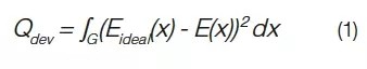
G is the area of ​​interest, Eideal(x) is the desired illuminance distribution target, and E(x) is the current light distribution.
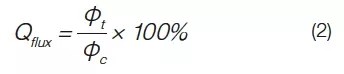
The flux-preferred function Q flux corresponds to maximization, which is quantized to the flux in the target region required for the ratio of the Φ flux, and the φC available flux is collected by the optics.
Mathematical representation of the optical surface
NURBS
NURBS technology is very mature and can be used in computer-aided graphics systems as well as ray tracers. Because of its flexibility, you can easily manipulate or modify surfaces by changing control points or their weight during the optimizer. The NURBS surface is a parameter tensor product surface and is defined as follows:
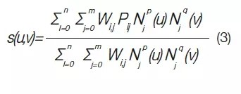
Where P ij is a rectangular array of control points, where P ij is a (n + 1) × (m + 1) matrix, wi, j is a weight, N ip (u) and N jq (v) are bases of u and p The function, the v direction, is associated with the knot vector, respectively.
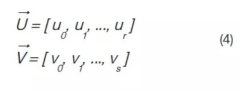
Where r = p + n + 1 and s = m + q + 1 holds. When a control point must be added in NURBS, the junction insertion method is used to complete the control point. Adding a single node requires adding an entire column or a row of control points. It is also impossible to remove the knot without using NURBS without changing the geometry. This local refinement is mainly limited to NURBS because its tensor product structure is shown in EQ3. As shown in Figure 3, the NURBS surface is repeated line by column horizontally and vertically. To satisfy this balance, if you add a new control point, add an entire column or a row of control points.
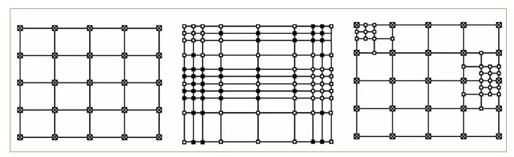
Display an example of the initial 5x5 NURBS patch (left), how to add control points along rows and columns when NURBS (middle) and T-spline (right) are completed after modification
ZGAR TWISTER Disposable
ZGAR electronic cigarette uses high-tech R&D, food grade disposable pod device and high-quality raw material. All package designs are Original IP. Our designer team is from Hong Kong. We have very high requirements for product quality, flavors taste and packaging design. The E-liquid is imported, materials are food grade, and assembly plant is medical-grade dust-free workshops.
Our products include disposable e-cigarettes, rechargeable e-cigarettes, rechargreable disposable vape pen, and various of flavors of cigarette cartridges. From 600puffs to 5000puffs, ZGAR bar Disposable offer high-tech R&D, E-cigarette improves battery capacity, We offer various of flavors and support customization. And printing designs can be customized. We have our own professional team and competitive quotations for any OEM or ODM works.
We supply OEM rechargeable disposable vape pen,OEM disposable electronic cigarette,ODM disposable vape pen,ODM disposable electronic cigarette,OEM/ODM vape pen e-cigarette,OEM/ODM atomizer device.


ZGAR TWISTER Vape,ZGAR TWISTER Vape disposable electronic cigarette,ZGAR TWISTER Vape pen atomizer ,ZGAR TWISTER Vape E-cig,TWISTER Vape disposable electronic cigarette
Zgar International (M) SDN BHD , https://www.zgarecigarette.com