The appearance of stealth aircraft has promoted the development of anti-stealth technology. One current method of anti-stealth is to reduce the traditional radar frequency to the L, UHF, VHF or even HF bands in the electromagnetic (EM) spectrum. Another promising method is to raise the frequency band to a higher infrared (IR) band where passive sensors can detect thermal radiation emitted by each object. In the future, with the improvement of the capabilities of infrared (IR) missiles, infrared search and tracking (IRST) systems, true low observability will not only need to be hidden in radar multiband but also need to achieve stealth in the IR band.
The infrared band can technically extend from the top of the 300 GHz EHF radio band to the visible band beginning at 430 THz, with wavelengths ranging from 1 mm to 0.77 μm. However, the available spectrum is currently limited to 0.77 to 14 μm. It is further divided into three sub-bands: near-infrared (NIR) of 0.7 to 1.5 μm; medium-wave infrared (MWIR) of 1.5 to 6.0 μm and long-wavelength infrared (LWIR) of 6 to 14 μm. ). The exact limits will vary, and a short-wavelength infrared (SWIR) region can be included in the 0.7-3.0 μm range.
Infrared search and tracking (IRST) works in the MWIR and LWIR ranges. Early air defense missiles were operating in the near-infrared (NIR) section, but now they are almost entirely in the MWIR section, and the wavelength used is constantly increasing.
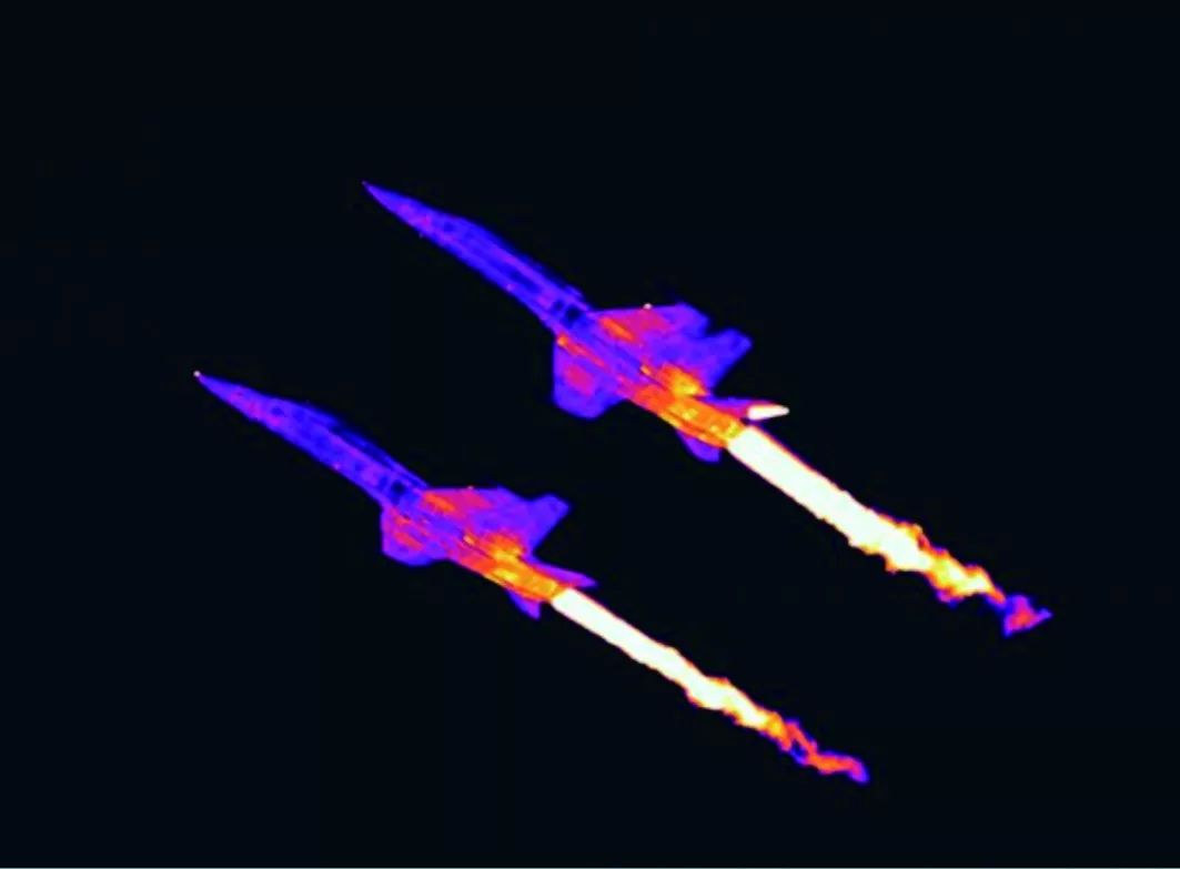
The image of the US Navy Blue Angels F / A-18 in the low-middle-infrared infrared image shows that the radiation intensity of the engine plume is significantly higher.
Infrared sensor upgrade
The detection range of infrared sensors is continuously improving, and will develop in the direction of more effective wavelengths and more granular detection arrays. Infrared signals will vary in shape, material, observation angle, speed, background, environment and altitude. And sensor wavelength varies. The main sources of infrared signal emission include the hot parts of the engine, the exhaust plumes of the nozzles, and the fuselage of the aircraft, as well as reflections of sunlight, sky and ground. Therefore, the United States stealth aircraft suppress infrared signals by covering the engine's heating components, cooling the exhaust, reducing the plume, and using a low-emission surface coating.
Work step
There are several different types of infrared sensors that correspond to different wavelengths of radiation-sensitive materials in the band. Uncooled lead sulfide (PbS) detectors operate at 2 to 3 μm. The cooled lead sulfide or uncooled lead selenide (PbSe) detector operates in the 3 to 4 μm range. New sensors that cool lead selenide, indium gallium or mercury cadmium telluride (HgCdTe) can operate in the 4-5 μm band. Cadmium mercury cadmium can also work in the LWIR section with micro heat detectors and quantum well infrared photo detectors. In addition, the detection range also benefits from the integration of focal plane arrays. As the number of detectors increases, so does the resolution.
In the IR region, all objects above absolute zero emit radiation. As the temperature rises, the total amount of radiation will increase in the fourth degree of K at K/degree Celsius and the radiation will propagate through the wavelength, and the higher the temperature, the shorter the wavelength of the radiation curve. The maximum radiation wavelength of the object at 20°C (68°F) is 9.9μm, and the maximum radiation wavelength of the object at 1000°C is 2.3μm.
The amount of radiation also depends on the material. The “emissivity†indicator represents the ratio of the radiation of a material at a given temperature to a perfect radiator (known as a “blackbodyâ€) with a theoretical emissivity of 1 and the emissivity does not generally vary with wavelength, but corresponding materials can be designed. Moreover, temperature and emissivity together determine the "radiance" of the material, ie the amount of emissions per unit area. The "strength" of an object with respect to the sensor, ie, the signal strength, depends on its projected area at the sensor because the detector responds to "irradiance" or the concentration of the emission. Therefore, the IR intensity of an object depends on the angle of view being detected, and since the sensor is probed from the center of the sphere, the amount of radiation always decreases with the square of the distance.
In addition to launching thermal radiation, the aircraft also suffers from radiation from the sun, the sky, and the ground, respectively, known as sunlight, sky-scattered light, and earth-backlit light (abbreviated as ground or ground light). Controlling the IR signal requires consideration of emission and reflected radiation. Due to the law of conservation of energy, all incident radiation must be absorbed, propagated, or reflected. The emissivity is always equal to the absorptivity, and the material is usually too thick to emit. If the emissivity decreases, the reflectivity increases.
But radiation must reach the sensor to be detected. Due to the molecular absorption and specular scattering mainly caused by water vapor and carbon dioxide, the wavelengths transmitted in the atmosphere are shorter than the wavelengths transmitted in other media, and the two become more and more dense with the pressure, the more concentrated the gas, “absorption The deeper and wider the belt is. The water vapor density also varies with temperature, but it is very thin at 9150 m (30000 ft) or more and becomes negligible. In fact, this absorption detection is limited to 2-5 μm and 8-14 μm “atmospheric windows†of MWIR and LWIR, implying that the detection range is always worse at lower elevations and angles.
Finally, the sensor must distinguish the target from any background radiation or path radiance between them. Ground radiation depends on the vegetation and temperature and may have a greater intensity than the target. The light of the sky changes with the passage of time and with the increase of latitude. Clear skies may be good for detecting aircraft, and clouds can block IR radiation and reflect sunlight with greater intensity than the target. When the frequency band is lower than 3μm, the main source of the path radiation is the sunlight scattered by the aerosol; when the frequency exceeds 3μm, the heat scattering of the air increases to the end of the MWIR band.
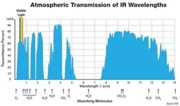
Atmospheric transmission infrared wavelength
Overall IR signal level
The overall IR signal level (IRSL) of the target is the sum of the signals of all its parts. The signal for each component depends on its radiometric contrast with the background and path, the projected area on the sensor, the degree of atmospheric attenuation of the emission wavelength (which, together with the contrast and projected area, determines the "contrast intensity" of the component) and the sensor The ability to respond to these wavelengths. Therefore, the main determinant of the aircraft's IRSL depends on the viewing angle and sub-band.
In the MWIR segment, the IRSL at the rear of the aircraft is the largest and the front is the smallest. The infrared signal from the rear end is mainly caused by the engine's "hot parts", ie the nozzle center body, the inner wall and the rear end face of the low-pressure turbine. The temperature of these components is between 450 and 700°C, ie the nozzle and exhaust. The temperature of the plume. This is why almost all infrared-guided air defense missiles work in the MWIR segment.
At a quarter of the back of the fuselage, the hot component is still the main contributor to the infrared signal. The same is true of exhaust plumes, but it is not as obvious as people think. Unlike solids, gas molecules oscillate freely, which allows them to emit and absorb energy under specific "spectrum lines." Since the main products of hydrocarbon combustion (water vapor and carbon dioxide) are also in the atmosphere, the absorbed plumes dissipate more heat than other signal components. However, the high temperature and pressure of the exhaust gas increased the absorption line of carbon dioxide to 4.2 μm, and produced sharp peaks at 4.15 μm and 4.45 μm. But the atmosphere will still make them decay, especially at low altitudes.
From the side, the signal strength of the plume is the greatest. It can extend over 15m (50ft) behind the aircraft, but its radiation is mainly concentrated in front of 1.37m (4.5ft). With the increase of sensor projection area, the fuselage has also become a major signal contributor. The nose, leading edge of the wing and air inlet are the main parts. Because the plume expands radially along the nozzle axis, the plume is still visible despite the rapid decrease in temperature.
In the LWIR segment, the biggest problem is the fuselage. Due to the front aerodynamic heating and the rear engine heating, the body temperature may reach 30 °C ~ 230 °C. Although there is less radiation than the tailpipe, the projected area of ​​the rear fuselage is 10 times larger. As the height decreases, the influence of the ground light is also expanding, and the reflected ground light and the sky scattered light are also important items in the LWIR segment, especially for the low radiation surface and the aircraft viewed from above or below. In the near-infrared (NIR) region, reflected sunlight is the main driving force for IRSL at most angles. The plume has little effect on the LWIR or NIR segments.
IRSL is greatly affected by speed. When the engine is in a non-applied state, the exhaust pipe and the rear fuselage generally have a greater signal emissivity than the plume. In the forced state, the afterburner greatly expands the plume, doubles the temperature of the exhaust pipe, and raises the rear fuselage temperature by approximately 70°C. These effects can increase the IRSL by nearly 10 times.
The fuselage, especially the leading edge of the wing, also heats up quickly due to high speed. At a height of 9144m (30000ft) flying at Ma0.8, the skin temperature may be 11% higher than the ambient temperature, but when the speed reaches Ma1.6, the skin temperature can be 44% higher than the ambient temperature, higher than the detection Twice the range. That is to say, when an aircraft is flying at supersonic speed, it will produce a “Mach cone†that compresses and heats air, which can increase the contrast of this area with the background by an order of magnitude, which is more than double the detection range.

Infrared emissivity changes with temperature
There is no public IRSL data on modern combat aircraft, and considering all the factors, IRSL does not have a simple metric such as Radar Cross Section (RCS) that is detectable. For benchmarking, Sukhoi’s company believes that the OLS-35 MWIRIRST on the Su-35 can detect a Su-30 size target from the rear of 90km (56 miles) to the front 35km. However, the Su-30 is a large twin-engine aircraft that cannot effectively suppress the IR signal. Theoretically, the infrared-guided surface-to-air missile can capture it as a target.
IR suppression of aircraft usually begins with the engine. The signal at the hot end part is most easily suppressed by the shield, mainly by increasing the mixing of the exhaust gas and air to reduce the plume, thereby reducing the temperature and pressure more quickly. Common techniques include increasing the engine's bypass ratio and injecting cooler air, steam, or carbon particles into the exhaust. Another method is to increase the nozzle with V-shaped, fan-shaped or corrugated seals to promote the radial spread of the plume and mix with the air. The trailing edge of the V-shaped nozzle can also generate a detached vortex to accelerate the mixing. These additional components also reduce noise emissions, which is why the engine of the new passenger aircraft is equipped with V-shaped exhaust nozzles.
Using a low emissivity material can reduce the skin's emission. Theoretical studies show that reducing the emissivity of the skin from 1 to 0 can reduce the detection range by half. Layered materials with different refractive indices can cause the surface to reflect only specific wavelengths and emit at other wavelengths, such as those with greater atmospheric attenuation. Of course, the surface coating on stealth aircraft must also take into account its radar effect.
Leopard Urine and Platypus
IR inhibition is part of the study of low observability measures that the United States has continued for half a century and is usually combined with the purpose of reducing the rear radar cross-sectional area (RCS). The CIA’s A-12 was the first aircraft to use signal control design as the main standard, and was the first aircraft in the United States to contain the rear RCS of the aircraft and reduce its exposure to infrared missiles. Due to the round, open titanium nozzles and a large amount of exhaust plumes, radar and IR signals at the rear of the aircraft are inherently large.
Lockheed once jokingly added that he had to add “Panther Piss,†but later decrypted CIA documents revealed that it refers to cesium fuel. It can ionize the exhaust plume, reducing the RCS of the last quarter of the body, and it also interferes with the infrared-guided missiles of the time. The principle may be that the radiation in the NIR and MWIR sections is too strong, resulting in early sensors reaching Oversaturated and unable to work.
As the first stealth fighter that entered war, the F-117, with its low observability as the main means of its survivability, Lockheed did IR suppression on the body structure. The fuselage of the F-117 tilts rearward from the apex above the cockpit into a wide, flat appearance called "platypus". The engine exhaust flat rectifies into the horizontal and divides into 12 10.16 to 15.25 cm (4 to 4 inches). 6in) deep and 1.52m (5ft) wide slot (or channel). The angle of the lower fuselage tip is slightly upturned, and a 20.32 cm (8 in) lip is extended behind the vent. Covered with "heat-reflective" tiles, this is similar to the tiles used on the space shuttle and cooled by the engine's ducted air.
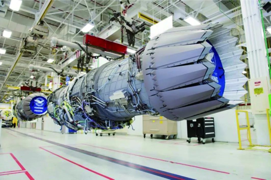
When designing the F135 engine, Pratt & Whitney aims to design a wedge nozzle like the F-22. The outside of the nozzle contains micropores to provide cooling air and, like F119, overlaps to create a serrated trailing edge, which directs the exhausted vortex into the exhaust and shrinks the plume. Internal and external surfaces may be absorbed by low emissivity radar waves .
The "platypus" shields hot metal parts while the flat plume reduces IR intensity from the side and accelerates mixing with the ambient air. The extended lip masks the exhaust slots and the plumes in the front 20.32 cm (8 in) section from below, while the low emission tiles limit infrared absorption and emission.
As far as the F-117 is concerned, engineers are also faced with the difficulty of balancing the need to suppress radar and IR signals, extreme heat and pressure tolerance, and it is said that the "platypus" is the hardest part of the design. Heat has been causing structural distortions. Eventually, a structural expert designed a "tile-like" panel that slides against each other to accommodate thermal expansion.
The B-2 Stealth Bomber retains the IR suppression technology of many stealth fighters. The B-2's engine is buried in the wing to prevent heating of the external surface. Exhaust is cooled by ducted air, including the use of secondary air intake, and is rectified into a flat stream prior to discharge from an "aft" deck made of titanium covering a low emissivity ceramic tile. A few feet behind the spout is likely to use magnetic radar absorbing material (RAM) to block plume core flow from below and to the side. In addition, both the engine cowling and the tail section terminate in a large V-shaped structure flap that induces a detached vortex.
This tail section has proved to be one of the main reasons for the increase in maintenance costs and the time-consuming maintenance of aircraft. By the late 1990s, a new ceramic tile was developed and a new coating was applied to the tail-spray for the situation where the blisters on the edge of the exhaust port and the erosion rate of the magnetic RAM were faster than expected for multiple B-2s. On the tube, but the cracks in the tail section continue. Later, all 21 B-2s had the same problem. Temporary repairs were made to these B-2s, including protective covers for the tiles. Long-term solutions were also being developed during the same period. By the end of 2010, there were third-generation tails.
Turbine shield and surface coating
The F-22 and F-35, which are five-generation machines, are required to meet a number of requirements such as increased engine, supersonic cruising and fighter agility, and less maintenance. Both of these stealth fighter jets use similar IR suppression techniques on the internal parts of the engine, the tail structure and the fuselage coating, but there is a big difference in nozzle design.
The horizontal tail of both aircraft extends far behind the tail nozzle, and the exhaust and plume restrict the view from the side to the rear quarter in the azimuthal plane. Both engines have a stealth booster section. The rear of the low pressure turbine is a thick, curved guide vane that blocks the nozzle and does not look directly into the hot rotating turbine assembly. The fuel injector is integrated into the vane blades and replaces the fuel boom and flame stabilizer of a conventional afterburner. The guide vane shields the turbine and has tiny holes that introduce cryogenic cold air.
Both aircraft are also coated with an IR-reject coating. The F-22 was precision machined with a polyurethane-based "IR topcoat" for low observability. This IR coating was also included in the F-16 "Have Glass" signal reduction project. . The F-22 may also use fuel to cool its leading edge.
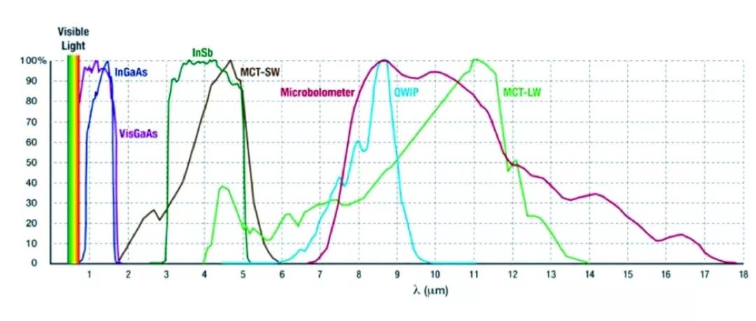
The relative response of the infrared detector material is the wavelength on the horizontal axis and the relative sensitivity on the vertical axis.
Although the radar absorbing material (RAM) on the F-35 skin has fiber mats, Loma still uses a newer robotic system to build polyurethane-based RAM coatings for the aircraft. Project officials said that the outermost coating has better abrasion resistance, and the MWIR image of the F-35 also shows that the coating has low emissivity. Coatings of both aircraft still exhibited poor wear resistance and temperature resistance, and required concentrated time for recoating the coating more frequently than expected. The US Air Force announced in 2015 that it is testing the new F-35 coating, which will have better wear resistance and temperature resistance.
Although the exact composition of the coating is unknown, the material commonly used as a matrix is ​​polyurethane because of its high durability, adhesion, chemical resistance, and climate suitability. Its natural emissivity is 0.9, but many fillers have been shown to reduce emissivity in composites. For example, adding bronze can reduce the emissivity to less than 0.07, despite the sacrifice of higher conductivity and radar reflectivity. The 5-500 μm multi-layer glass microspheres diffused at a weight of 50% to 70% can achieve low emissivity at the selected wavelength and may be radar-neutral. Iron oxide also has an emissivity in the range of 0.16 to 0.28, and the emissivity of the polyurethane-based composite material exhibits less than 0.5.
Wedge and tail feathers
The "non-axisymmetrical" of the F-22, ie the two-dimensional thrust vector nozzle, has an upper surface and a lower surface that end in a wedge shape with the mixing center edges. These wedge-shaped nozzles further mask the hot end parts of the engine while rectifying the exhaust plume to a flat flow and generating vortices. Many tiny holes are visible on its inner surface and may be used to provide ducted air for cooling. It is believed that wedge-shaped nozzles are effective at reducing the signal, but they are also a major part of the "raptor"'s maintenance costs and workload (the internal jet nozzle is one of the most frequently replaced parts in conventional fighter maintenance). Therefore, when designing the F-35 (JSF project), engine and airframe manufacturers are also looking for more economical methods.
At the end of 1996, when the JSF bid was still in progress, competitors of the two engines tested the axisymmetric design, aiming at masking the signal of the wedge nozzle at all costs. Pratt & Whitney tested low observable asymmetric nozzles (LOANs) on the F-16C. Tests have shown that IR signals are significantly reduced in the RCS and IRSL segments. The known LOAN project incorporates forming, special internal and external coatings, and "advanced cooling systems," which are expected to more than double the useful life of the nozzle.
In early 1997, GE tested a similar low observable axisymmetric (LOAxi) exhaust system on the F-16C, achieving its signal shielding goal. According to GE, the LOAxi spout interior includes overlapping diamond shaped coatings and slot injectors to provide cooled air to the body. Improvements in RCS design and material technology have enabled axisymmetric nozzles to match the characteristics of a two-dimensional exhaust pipe while halving the weight and costing 40%.
Pratt & Whitney's F119 engine uses a number of techniques to reduce the plume and limit the F-22's IR signal. The end of the blade can be seen in the figure, which blocks the direct view of the low pressure turbine and contains tiny holes that inject colder air into the exhaust port. The "wedge" nozzle also flattens the exhaust gas and reduces the plume by narrowing the side air by mixing the exhaust with the ambient air.
The jets on the F-35 fitted Pratt & Whitney F135 engine come from these methods. It consists of two sets of overlapping tabs, 15 in each group. The outer tabs are centered on the gap between the inner tabs. The medial tabs are thin, with a metal sheath and straight edges, and the ends are inverted V-shapes. When the nozzle is fully open, the sides form a rectangular gap.
The outer flaps that are "tail feathers" are thicker and covered with porcelain tiles with mixed crystal faces. They terminate at a V-shape that overlaps with the ends of the inner tabs to create a serrated edge. To the direction of the fuselage, the ends of the tiles are four V-shaped, and there are additional tiles covering the two adjacent in a zigzag manner.
The F135 nozzle is likely to suppress IR signals by a variety of methods. The trailing V-shape creates a detached vortex that shortens the plume, while its steeper axial angle may cause colder ambient air to enter the exhaust flow path. The inner surfaces of the two sets of flaps are white and contain tiny holes similar to those on F119, which provide cooling air. Some reports mention the presence of injectors between the tail feathers and the V-shaped flaps to provide more cooling air. Tiles and inner flap surfaces are likely to consist of low emissivity RAM composites. The trailing edge of the central fuselage also terminates in a small V-shape, which may further increase the vortex strength of the air flow.
The achievements of these IR suppression efforts are difficult to quantify. Infrared cameras regularly record the flight status of stealth aircraft at airshows, but in such a close range, the image masks the inhibition of atmospheric absorption. After the start of the F-22 IR signal test in 2000, Air Force officials stated that the "Raptor" will exhibit "a very low omnidirectional IR signal under constant supersonic conditions." At the 2016 Farnborough Air Show, some images captured from the F-35 infrared sensor manufacturer FLIR show that the F-35 effectively suppresses the heating of the engine airframe and the emission of IR signals emitted by the nozzles. There is no doubt that IR sensors are improving, but people are also taking measures to suppress IR signals.
Mono Solar Panel
Anti-reflective coating: AR used reduces the reflectivity to enhance transmittance.
Tempered Glass: Low Iron and AR coating glass increase the power output and mechanical strength of the solar module. Mechanical load ≥2400Pa, transmittance ≥91.6%
EVA: Transmittance ≥91%, Adhesive Capacity >85%
Cell: 17.9% of high-efficiency solar cells to sure 15.7% module efficiency
Back sheet: Using higher quality back sheet to prevent destroying and water, it`s reflectivity ≥87%, peeling strength ≥ 40N/cm.
Aluminum Frame: Anodized aluminum alloy to effectively improve the corrosion resistance and strength
Mono Cell Solar Panel,Monocrystalline Module,Perc Mono Solar Panel,Monocrystalline Solar Panel Price
Wuxi Sunket New Energy Technology Co.,Ltd , https://www.sunketsolar.com