Inductance, has always been a little mysterious: it can generate a magnetic field, the magnetic field and the electric field are connected; the current I of the inductor can not be abrupt, but the current change rate dI/dt can be abrupt; the energy storage of the inductor is related to the current flowing through it.
Ferrite and iron powder are two core materials used to switch the power supply inductance. The energy storage inductor applied to the power supply is typically made into a closed loop such that the entire magnetic field is contained within the inductor, so the flux size and the stored energy of the core will characterize the core material.
Take the output inductor of the Buck circuit as an example. The core of the inductor has a certain DC component, and the applicable materials are:
(1) Iron powder core
The fine powder and insulating material composed of the milled iron powder and other alloys constitute a magnetic powder core. The insulating particles around the iron powder particles constitute the inherently dispersed air gap of the iron powder core.
(2) Ferrite core with air gap
The inductance of the Buck circuit has a certain DC component. If the air gap is not opened, the ferrite core is extremely easy to saturate. After the air gap is opened, the magnetic flux of the closed magnetic circuit will increase rapidly. Since the relative magnetic permeability of air is 1 and the relative magnetic permeability of the core material is several thousand or more, most of the energy in the core will be stored in the air gap flux.
The air gap reduces the effective magnetic permeability of the core, and the entire BH curve is tilted, increasing the magnetic field strength H at saturation, and the core is less likely to saturate. Figure 1 shows the BH curve without air gap and open air gap.
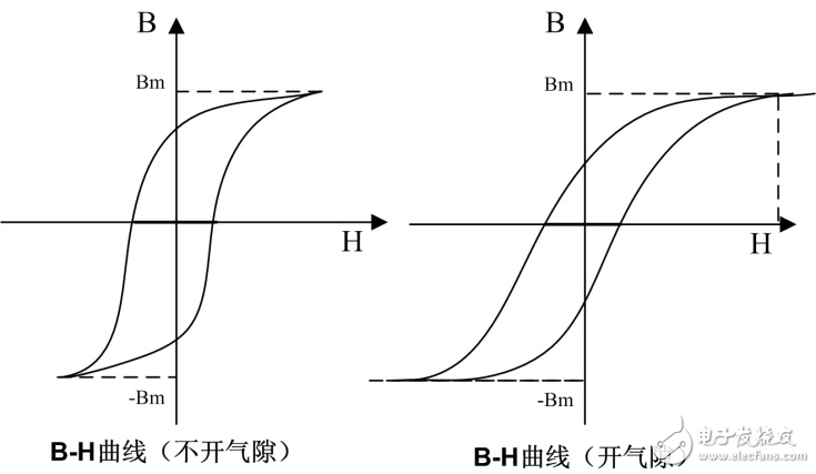
Figure 1 Inductance BH curve
In general, we will find that most inductors with ferrite design have a core loss of only 5% to 10% of total inductor loss (coil plus core loss). However, if the inductor uses an iron powder core, the value will increase to 20% to 30%.
First, the inductance: the saturation of the core
When the current (or magnetic field strength) flowing through the inductor is greater than a certain value, the core of the inductor may be saturated. When it is saturated, its sensitivity will decrease and be close to zero.
The voltage waveform on the current limiting resistor of a flyback circuit is shown in Figure 2 (the primary and secondary of the transformer in the flyback converter can be seen as a pair of coupled inductors). The current waveform flowing through the primary inductor can be seen from the figure. As the current increases, the inductance gradually saturates and the inductance decreases, causing the slope of the waveform of the trapezoidal current to increase.
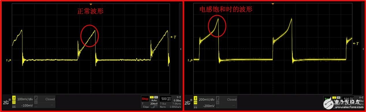
Figure 2 Inductance saturation waveform comparison
Second, the inductance: leakage of magnetic flux
An important characteristic of an inductor is flux leakage. Unshielded inductors (such as air core inductors, rod inductors, I-shaped inductors, ring-shaped air gap inductors, etc.) can cause flux leakage. These are potential sources of EMI.
In particular, the magnetic field of the air gap in the energy storage inductor may interfere with other components of the system. If an open air gap core is used, in order to minimize magnetic field leakage, a large core with a small air gap is better than a small core with an air gap.
When the two inductors L1 and L2 are close to each other, the flux leakage will create a mutual inductance between the two. The magnetic field generated by the first inductive circuit energizes the second circuit. This process is similar to the interaction between the primary and secondary coils of the flyback transformer. When two currents interact through a magnetic field, the resulting voltage is determined by the mutual inductance LM:

In the formula, V2 is the error voltage injected into the circuit 2, and I1 is the current flowing through the circuit 1 in the circuit 1. The LM is very sensitive to circuit spacing, inductive loop area, and loop direction.
Therefore, the principle of the arrangement of the inductors is:
(1) correctly arrange the direction of the inductor so that it is at a right angle to minimize crosstalk between the inductors;
(2) The inductance spacing should be as far as possible.
The ZY78xx series module power supply developed by Zhou Ligong Zhiyuan Electronics is designed with full consideration of the choice and layout of the inductor, and the optimal balance between space volume and performance parameters. This series completely replaces the LM78xx series chip, which has the advantages of high efficiency and small size.
Figure 3 ZY78xxS-500 series
Usb Common Mode Choke,Magnetic Ring Inductor,Wurth Inductor,Coilcraft Inductor
IHUA INDUSTRIES CO.,LTD. , https://www.ihua-sensor.com