The HL-SRS3D sound field processor designed and manufactured by SRSM62434F can fully realize SRS3D (SRS three-dimensional stereo field, i.e. analog home theater) and SRSMono (SRS mono) analog stereo effects. Among them, the straight-through mode is suitable for audio sources that have been processed by SRS3D or non-standard stereo recording audio sources; the SRS3D mode is suitable for standard stereo sound sources such as Dolby AC-3 signal source and other encoded signals; , TV audio signals, etc.
The HL-SRS sound field processor can be used as an independent sound effect processor installed between CD, VCD and other signal sources and power amplifiers, and can also be used directly in the original CD, VCD, power amplifiers, only need to connect the signal input, The output line is sufficient. When it is installed in the original power amplifier, the input and output of the volume potentiometer of the power amplifier are disconnected, the input is connected to the signal input terminal of the processor, the output (the center tap of the potentiometer) is connected to the signal output of the processor, and the power supply of the processor is connected The power supply of the power amplifier is sufficient. For the sake of reliable remote control, install the infrared receiving head close to the hole on the front panel. The installation position in the processor is the key to improve the installation quality. It can be adjusted according to the actual situation, so as not to affect the signal-to-noise ratio of the original machine. When installing in the VCD machine, just connect it directly to the VCD audio terminal.
The principle circuit of the HL-SRS sound field processor is shown in Figure 1.

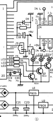

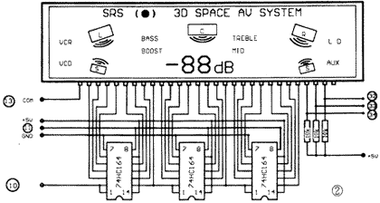
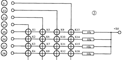
Figure 2 shows the LCD display and drive display circuit. The circuit can display the volume, tone, sound field, and decibels of the center level. Normally, the decibel number of the main volume is displayed. When adjusting the tone, the currently adjusted high and low decibel numbers are displayed. When adjusting the sound field in the center sound space, the adjusted level decibel number is displayed. When in the SRS3D playback mode, the circuit displays a five-channel sound field graph, and when adjusting each function parameter, the corresponding display flashes on the screen. The display is driven by 74HC164 and CPU {32}, {33}, and {34} pins, and is designed for a single COM terminal. The â‘ pin of the display screen is the COM terminal, connected to the CPU {13} pin. The display is negative, and the background light supply voltage is 8V. If you use 9V power supply on the SRS processor, you should consider connecting two diodes 1N4001 in series, and add a heat sink for the three-terminal voltage regulator integrated circuit AN7809. You can also draw a power supply from the 5V voltage stabilizer on the SRS board to add AN7808 supplies power to reduce the load on AN7809.
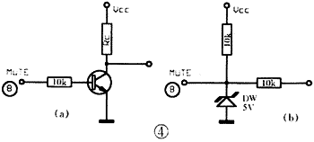
Figure 3 shows the keyboard matrix composed of the pinout lines of the {21} ~ {28} pins of the CPU. The {25} ~ {28} feet are pulled up through a 10k resistor to form a 16-key keyboard. Figure 4 shows two output interface circuits, which are suitable for the mute of the "low level" and "high level" of the subsequent stage. DW is a 5V voltage stabilizing diode, which is used to avoid damage to the CPU if the interface voltage is higher than 5V.
The {14} foot of the sound field processor CPU introduced in this article can forward the remote control signal received by the processor. When installing in the VCD machine, the signal output line of the infrared receiver head of the VCD machine can be disconnected, and the signal is transmitted from the lead of the receiver head to the {12} pin of the CPU, and the {14} pin is then forwarded to the signal output line. That's it. In this way, the receiver can reliably control the overall operation of the processor and VCD. The SRS board can be connected to the VCD audio output terminal.

Follow WeChat

Download Audiophile APP

Follow the audiophile class
related suggestion
