The power switch is widely used in computers, communications, electronic instruments, industrial automation, national defense and household appliances because of its advantages of low power consumption, high efficiency, small size, light weight, stable operation, safety and reliability, and wide voltage regulation range. And other fields. However, the switching power supply has poor transient response and is prone to electromagnetic interference, and the EMI signal occupies a wide frequency range and has a certain amplitude. These EMI signals pollute the electromagnetic environment through conduction and radiation, causing interference to communication equipment and electronic equipment, thus limiting the use of switching power supplies to some extent. The interference sources in the switching power supply are mainly concentrated in voltage and current changes, such as switching tubes, diodes, high-frequency transformers and other components, as well as AC input and rectifier output circuit parts. Next, I will talk about the five major measures to suppress the electromagnetic interference of the switching power supply.
AC input EMI filter
There are usually two ways in which the interference current is transmitted on the wire: the common mode and the differential mode. Common mode interference is the interference between the carrier fluid and the earth: the interference size and direction are the same, and exist in any relative ground of the power supply, or between the neutral line and the earth, mainly generated by du/dt, and the di/dt also produces a certain total. Mode interference. The differential mode interference is the interference between the carrier fluids: the interference is equal in magnitude and opposite in direction, and exists between the power phase line and the neutral line and between the phase line and the phase line. When the interference current is transmitted on the wire, it can be either common mode or differential mode; however, the common mode interference current can only interfere with the useful signal after it becomes the differential mode interference current.
The above two types of interference exist on the AC power input line, usually low-band differential mode interference and high-band common mode interference. Under normal circumstances, the differential mode interference amplitude is small, the frequency is low, and the interference caused is small; the common mode interference amplitude is large, the frequency is high, and the radiation can be generated by the wire, and the interference caused is large. If an appropriate EMI filter is used at the input end of the AC power source, electromagnetic interference can be effectively suppressed. The basic principle of the power line EMI filter is shown in Figure 1. The differential mode capacitors C1 and C2 are used to short-circuit the differential mode interference current, while the intermediate connection grounding capacitors C3 and C4 are used to short-circuit the common mode interference current. The common mode choke is composed of two coils that are equal in thickness and wound in the same direction on a magnetic core. If the magnetic coupling between the two coils is very tight, the leakage inductance will be small, and the differential mode reactance will become small in the power line frequency range; when the load current flows through the common mode choke, the series The lines of magnetic force generated by the coils on the phase line are opposite to the lines of magnetic force generated by the coils connected in series on the center line, which cancel each other out in the core. Therefore, even in the case of a large load current, the core does not saturate. For the common mode interference current, the magnetic fields generated by the two coils are in the same direction, which will exhibit a large inductance, thereby attenuating the common mode interference signal. Here, the common mode choke coil is made of a ferrite magnetic material having a high magnetic permeability and a good frequency characteristic.
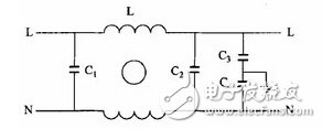
Figure 1 Basic circuit diagram of power line filter
Improve the switching waveform with the absorption loop
During the turn-on and turn-off of the switch or diode, due to the transformer leakage inductance and line inductance, the diode storage capacitor and distributed capacitance, it is easy to generate a spike voltage at the collector, emitter and diode of the switch. The RC/RCD absorption loop is usually used, and the RCD surge voltage absorption loop is shown in Figure 2.

Figure 2 RCD surge voltage absorption loop
When the voltage on the absorption loop exceeds a certain range, the devices are quickly turned on, thereby venting the surge energy and limiting the surge voltage to a certain amplitude. The saturable core coil or the microcrystalline magnetic bead is connected in series on the positive electrode lead of the collector of the switch tube and the output diode, and the material is generally cobalt (Co). When the normal current is passed, the core is saturated, and the inductance is small. Once the current flows in the opposite direction, it will generate a large back EMF, which effectively suppresses the reverse surge current of the diode VD.
Switching frequency modulation
The frequency control technique is based on the energy of the switching interference, which is mainly concentrated on a specific frequency and has a large spectral peak. If these energy can be dispersed over a wider frequency band, the purpose of lowering the peak of the disturbance spectrum can be achieved. There are usually two methods of processing: the random frequency method and the modulation frequency method.
The random frequency method adds a random perturbation component to the circuit switching interval, so that the switching interference energy is dispersed in a certain frequency band. Studies have shown that the switching interference spectrum changes from the original discrete spike interference to continuous distributed interference, and its peak value is greatly reduced.
The modulation frequency method adds a modulated wave (white noise) to the sawtooth wave, forms a sideband around the discrete frequency band in which the interference occurs, and expands the discrete frequency band modulation of the interference into a distributed frequency band. In this way, the interference energy is spread over these distributed frequency bands. This control method can well suppress the interference during turn-on and turn-off without affecting the operating characteristics of the converter.
One of the interferences of the switching power supply using the soft switching technology is the du/dt from the on/off of the power switch tube. Therefore, reducing the on/off of the power switch tube on/off is an important measure to suppress the interference of the switching power supply. The soft switching technology can reduce the on/off of the on/off of the switch.
If a small resonant component such as an inductor or a capacitor is added to the switching circuit, an auxiliary network is formed. Leading the resonance process before and after the switching process, the voltage is first reduced to zero before the switch is turned on, so that the phenomenon of voltage and current overlap during the opening process can be eliminated, and the switching loss and interference can be reduced or even eliminated. This circuit is called a soft switching circuit. .
According to the above principle, two methods can be used, that is, the current is zero before the switch is turned off, and no loss or interference occurs when the switch is turned off. This shutdown mode is called zero current shutdown; or the switch is turned on. Before the voltage is zero, no loss or interference will occur when the switch is turned on. This turn-on mode is called zero voltage turn-on. In many cases, turn-on or turn-off is no longer indicated. Only zero-current switches and zero-voltage switches are called. The basic circuit is shown in Figure 3 and Figure 4.

Soft-switching circuit control technology is usually adopted, combined with reasonable component layout, printed circuit board wiring and grounding technology, it can improve the EMI interference of switching power supply. The electromagnetic shielding measures are generally adopted to effectively suppress the electromagnetic radiation interference of the switching power supply. The shielding measures of the switching power supply are mainly for the switching tube and the high frequency transformer. When the switch tube works, it generates a large amount of heat, and it needs to be equipped with a heat sink, so that a large distributed capacitance is generated between the collector of the switch tube and the heat sink. Therefore, an insulating shielding metal layer is placed between the collector of the switching tube and the heat sink, and the heat sink is connected to the casing, and the metal layer is connected to the zero end of the hot end to reduce the coupling capacitance between the collector and the heat sink, thereby reducing Radiation interference from the heat sink.
For high-frequency transformers, the magnet-conducting structure should first be selected according to the shielding properties of the magnetizer. For example, the can-type iron core and the El-type iron core have good shielding effect of the magnetizer. When the transformer is shielded, the shielding box should not be placed close to the transformer, and a certain air gap should be left. If a multilayer shield with air gap is used, the resulting shielding effect will be better. In addition, in high-frequency transformers, it is often necessary to eliminate the distributed capacitance between the primary and secondary coils, and an open-loop ring made of copper foil can be placed between the coils along the entire length of the coil to reduce the disaster between them. In combination, this open circuit ring is connected to the iron core of the transformer and to the ground of the power supply to provide electrostatic shielding. If conditions permit, install a shield on the entire switching power supply, which will better suppress radiated interference.
Conclusion
As the size of switching power supplies is getting smaller and the power density is getting larger, EMI control issues become a key factor in the stability of switching power supplies. It can be seen from the above analysis that EMI filtering technology, shielding technology, sealing technology and grounding technology can effectively suppress and eliminate the interference and radiation between the interference source and the victim device, and cut off the propagation path of electromagnetic interference, thereby improving the switch. Electromagnetic compatibility of the power supply.
Constant Voltage Transformer,Laminated Transformer,Encapsulated Transformer,12V Ac Transformer
IHUA INDUSTRIES CO.,LTD. , https://www.ihua-magnetics.com