Ansoft Designe uses the latest Windows technology to integrate circuit simulation and electromagnetic simulation into an environment. It can be dynamically connected and co-simulated with electromagnetic simulation tools HFSS, Q3D, Slwave, and can also directly start HFSS in an Ansoft Designe environment. , Q3D, Slwave and run. Co-simulation can quickly calculate and optimize the electrical performance and structural parameters of the duplexer. It can accurately simulate the cross-coupling polarity and the far-end harmonics of the duplexer, thereby reducing the R&D workload and shortening the development cycle.
2. Co-simulation processIn this article we use a GSM base station duplexer as an example to illustrate the Ansoft Designe and Ansoft HFSS co-simulation diplexer flow.
We first divide the simulation of the duplexer into the following steps:
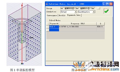
(1) The simulation of the eigen-frequency f0 for a single-cavity Q-turn, using symmetry to minimize the problem being solved.
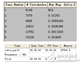
(2) Preliminary simulation of the window (simulation of the coupling coefficient K), using the Ansoft Designe and Ansoft HFSS co-simulation, the excitation mode solving method, so that the solution of the target value convergence in a shorter time, get a more accurate solution.
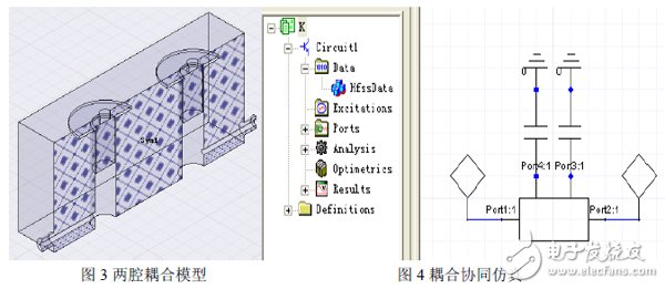
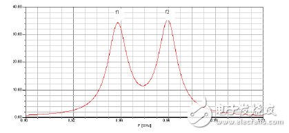
Apply formula 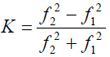 Calculate the coupling coefficient separately and determine the corresponding inter-cavity window size.
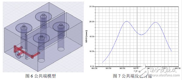
(3) Public end reflection delay simulation
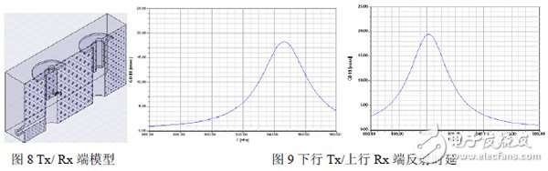
(4) Reflection delay simulation on the downstream (Tx) input, reflection delay simulation on the upstream (Rx) output.
Apply formula  , calculate the port delay,
 ![]() Coupling coefficient for normalizing source to first cavity
Coupling coefficient for normalizing source to first cavity
(5) The various components in the HFSS are cascaded and then imported into the Designe circuit block, as shown below.
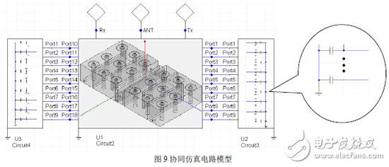
The λ/4 transmission line in the figure is used to correct the inter-cavity coupling:
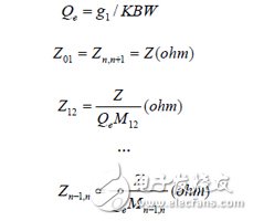
In the formula: ![]() For the external Q value, g1 is the component value of the Chebyshev low-pass filter-normalized prototype, which is the relative bandwidth.
For the external Q value, g1 is the component value of the Chebyshev low-pass filter-normalized prototype, which is the relative bandwidth.
(6) Optimization settings
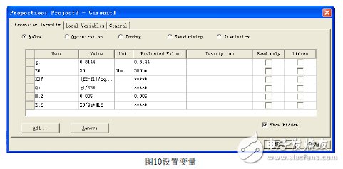
a. Set the variable
Click Design RationalTIes will pop up the dialog box as shown below, set the variable:
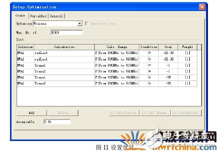
b. Set optimization
Right-click OpTImetrics Add OpTImizaTIon
After optimization, very satisfactory results are obtained. The frequency response curve is as follows:
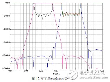
Look at the coupling coefficient M of the optimized variables, continue to optimize after modifying the dimensions, so that the M value will tend to zero or reach an acceptable value.
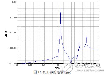
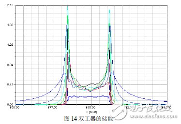
3. Comparison of simulation and test results (Broadening the bandwidth to meet the loss during actual debugging)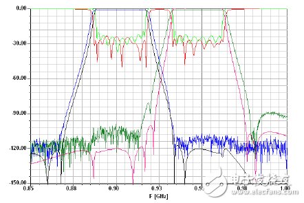
In this paper, the co-simulation of Ansoft Designe and Ansoft HFSS was used to successfully design a G-axis coaxial cavity diplexer with nine steps in the upstream and downstream respectively, which verified the high efficiency of the Ansoft HFSS and Ansoft HFSS co-simulation in the design and application of microwave devices. Collaborative simulation uses manual meshing, symmetry, and other functions and techniques to greatly reduce simulation time and improve simulation accuracy.
SHAOXING COLORBEE PLASTIC CO.,LTD , https://www.colorbeephoto.com