Overview:
Aiming at the new power standard issued by the national grid, this paper introduces the basic principle and scheme of low-cost smart meter design, and designs a low-cost smart meter based on HT46F49E single-chip and energy metering chip ADE7755, and adopts infrared with this scheme. data collection system. The system has been verified to work normally. The design is not only low in cost, simple in method, strong in anti-interference ability, but also has strong practicability and innovation.
As energy prices rise, standards for energy metering are getting higher and higher. The traditional inductive electric energy meter has the disadvantages of poor measurement accuracy, single function, small overload capability and poor anti-electromagnetic interference capability. In 2009, the State Grid introduced a new electric energy meter standard, in which the standards of the new electric energy meter are clear. Provisions. Inductive energy meters obviously can not meet the market requirements, facing the situation of being eliminated, and there is no unified standard for electronic energy meters that exist in the market early, and many of them do not meet the new standards of the national grid will also be eliminated. This will inevitably lead to a large number of new electronic energy meters that meet the new standards of national grid appliances. In this context, the author has designed a low-cost single-phase electronic energy meter scheme, which has proved feasible through practice.
1 Choice of the scheme The core function of the current energy meter is to measure and display the electric energy. Therefore, this paper only discusses several typical schemes of measurement and display that exist at present.
1.1 Measurement plan
1) MCU+ADC: The voltage and current are sampled by the ADC chip, and then multiplied is the active power. This method requires relatively high ADC chips, and the MCU (single-chip microcomputer) needs to perform a large number of calculations. The MCU also needs to deal with harmonics in the power grid, and the requirements for the MCU are also high, and the cost is high, and it is difficult to achieve high precision.
2) MCU+ energy metering chip: There are many energy metering chips on the market, such as ADE7755 and CS5463. These chips integrate high-precision analog-to-digital conversion, harmonic processing circuit, multiplier current, etc., which can convert electrical energy into pulses or It is another digital quantity, which greatly simplifies the design of the electric energy meter, and the measurement accuracy is high and the cost is acceptable. There is no special requirement for the MCU by this method, so this paper uses this scheme for system design.
1.2 display scheme
1) Counting circle: The pulse outputted by the energy metering chip drives the stepping motor, and then drives the counting circle to count. This method is simple, and is the same as the traditional induction meter display method, but the display content is too simple, it is prone to jam, and can not meet the requirements of the new energy meter.
2) Digital tube: It is the most simple and convenient display method, and it can self-illuminate, but the working current of the digital tube is too large, it can't work for a long time when it is powered by battery, and the national grid has strict requirements on the power consumption of the electric energy meter. Obviously not meeting the requirements.
3) Segment LCD: Segment LCD is commonly used in battery-powered devices such as calculators. The display content is relatively rich, and the power consumption is only uA level, which can greatly reduce the system power consumption, but it requires an external driver chip such as HT1621. Obviously, the segment LCD is an ideal choice.
2 System Introduction
2.1 System Solution The system is divided into two parts: the energy measurement part and the infrared data acquisition part, which are implemented on two circuit boards respectively. The following is divided into two parts:
1) Energy metering part: The system block diagram is shown in Figure 1. 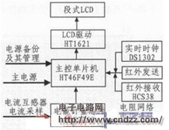
Figure 1 Energy metering block diagram
The ADE7755 chip samples the voltage and current, multiplies it to get the active power, and converts it into the corresponding frequency pulse. The single-chip counter counts the pulse as the user's power, and the microcontroller then controls the LCD to display the power. The infrared transmitting and receiving part of the block diagram 1 is used for the infrared meter reading, and the real-time clock is provided with the time base for charging the backup battery, and is also convenient for developing the multi-rate meter. The system adopts dual power supply. Under normal circumstances, the mains supply power to the system after step-down and linear power supply filtering. The single-chip detects the battery power. If the power is too low, the battery should be charged. When the power is off, the system is powered by the battery to ensure the power failure. The under-infrared meter reading is performed normally. In the power-off state, the data is stored in the EEPROM that comes with the microcontroller, which ensures the security of the data. 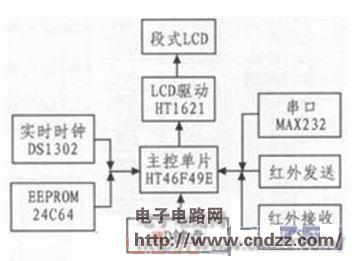
Figure 2 infrared data acquisition
2) Infrared data acquisition part: The system block diagram is shown in Figure 2. The AD keyboard inputs commands to the system, the infrared transceiver part completes the infrared meter reading or sends other instructions to the meter, and the collected data is saved by 24C64. Each user data occupies 8 bytes, and a total of about 1000 user data can be saved. . The real-time clock is used to insert time data for each user data. The serial port is used to communicate with the computer, and the collected data is sent to the computer for further processing to generate an electricity bill.
(Please read the PDF for details)
Valve Regulated Lead Acid Battery
Valve Regulated Lead Acid Battery,Lead Acid Battery,Vrla Battery,12V 200Ah Lead Acid Battery
Henan Xintaihang Power Source Co.,Ltd , https://www.taihangbattery.com