At present, the cable TV business is developing at a high speed. The CATV network will develop from the traditional one-way single (transmitting only TV signals) to the two-way interactive multi-function direction (INTERNET, Vod,
Data exchange, digital TV, digital broadcasting, etc.), the network structure has changed from a single cable network in the past to a fiber optic cable hybrid network (HFC), and the core of its development is from a unidirectional network to a bidirectional transmission network. Since it is a two-way transmission network, there is a reverse backhaul problem. The most prominent problem in a two-way CATV system is the problem of noise accumulation in the reverse transmission channel, the so-called "funnel effect".
1. The generation of noise Generally, the reverse channel transmits data signals. The main technical index of transmission is the bit error rate, and the HFC cable distribution network is composed of branch distributors. The transmission channel is shared by a large number of users, making it in a complex In the environment of electromagnetic waves, short-wave broadcasting, interference from household appliances, interference from industrial appliances, natural lightning interference, etc., the entire cable TV network is like a huge mesh antenna. Various interference enters the channel through the user port and the cable itself. The "funnel effect" formed by the return amplifier aggravates the carrier-to-noise ratio of the return channel, thereby greatly increasing the bit error rate.
Second, measures to suppress the noise of the return channel 1. Improve the shielding capacity of the coaxial cable distribution network to prevent interference from entering the cable. The user's terminal box and branch distributor must select products with good shielding function and high isolation. In addition, the coaxial cable network should have a good grounding system, and the grounding resistance should be less than 8 ohms.
2. Carefully design the cable distribution network to reduce the intrusion of external interference. We used to be familiar with the design of the forward transmission of the cable TV system, but we may still be more silent about the design of the reverse channel. Let's talk about the issues to be considered in the design of the reverse channel.
a. The difference between forward and reverse transmission loss of the signal transmission system.
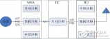
From the user terminal equipment to the front end will vary with time, temperature and location, most of which are cable losses between each branch along the return direction and the distributor port to the amplifier. Provide appropriate levels for forward transmission. In the case of backhaul, the level of the signal will be different, and the levels of the forward and reverse transmission channels are quite different. Now a branch of a distribution amplifier is used. Take the road as an example to illustrate, see Figure 1: 
The design of the forward channel is to select each branch according to the highest operating frequency, so that the signal level at the output port of each branch is consistent, so that each branch reaches a suitable level in the user's home, however, the return path loss There is a big difference, the data listed in Table 1 is a good illustration of it.
Table 1 Branch port number | T1 | T2 | T3 | T4 | T1 to T4 |
| 750MH branch port total loss | 27db | 25db | 26db | 27db | 0db |
| 40MHZ branch port total loss | 27db | 21.2db | 16.8db | 9.3db | 17.7db |
The above example shows that at the return frequency of 40MHz, the difference in return path loss for different ports can reach 17.7dB. Such a large difference requires that the front-end receiver has a large input range (large dynamic range), but the system has The carrier-to-noise ratio is limited, so it is not allowed when the return signal level is low. As in the above example, the return level of the first branch is set to 60dB, then the return signal of the fourth branch is The level is only 42dB. Obviously, when the signal returned from the fourth branch, the carrier-to-noise ratio does not meet the specifications. Generally, we require that the return signals sent by the user terminal equipment such as set-top boxes or CABLE MODEM must be close to the front end , So how to do this? That is, how to normalize the loss of each branch port? A simple and practical method is to use an equalizer. Because the equalizer is designed to cover the entire forward and reverse frequency band (5-750MHZ), the equalizer can correct the loss difference of the return channel and flatten the response of the forward channel. For example, a 6dB equalizer will attenuate 6dB at 5MHZ, and 4.6dB at 40MHZ, and 0dB at 750MHZ. This equalizer has an insertion loss of 1dB, so that the loss is 1dB at 750MHZ and 5.6 at 40MHZ. dB, and then analyze with the previous example, insert the equalizer at the port of each branch: as shown in Figure 2, return the attenuation value from each branch port to the amplifier at 40MHZ as shown in Table 2:
Table 2 Branch port numbers | T1 | T2 | T3 | T4 | T1 to T4 |
| 750MH branch port total loss | 27db | 26db | 27db | 28db | 1db |
| 40MHZ branch port total loss | 27db | 26.8db | 27db | 28.8db | 1.8db |
It can be seen from Table 2 that the equalizer greatly reduces the difference in the loss of the reverse channel and achieves the normalized path loss of the branch port. Another advantage is that it reduces the total aggregate noise entering the cable system. Without equalization (set the interference level to 20 dBmv), the interference intensity entering the first branch port is -7 dBmv, and the interference entering the last branch port is 10.7 dBmv; after using equalization, the level of all ports becomes- About 7dBmv, which makes the carrier-to-noise ratio of the entire system improved.
B. Fixed power method per HZ: The full-load backhaul system is composed of many channels, and the bandwidth and modulation method (QPSK, SQAM, etc.) occupied by each channel may be different, so how to allocate the appropriate power for each channel Ping? Because the laser input level of the return optical transmitter is strictly limited, when the level exceeds its maximum allowable input level, the laser will appear clipping and the signal will be seriously distorted. First of all, we have to analyze how much RF power can be added to the laser, and then allocate the total power to each channel according to the bandwidth occupied by each channel (the total bandwidth is 35MHZ). Here a fixed power distribution method per HZ can be used: First, the total power is evenly distributed from each HZ step to the entire return frequency band (the value of the step is determined by the highest input level that the laser can accept, If the maximum input level of the laser is 45dbmV, the average power per HZ step is -30DBMV. The algorithm is as follows: set the average power per HZ step to X, X = the maximum input level of the laser machine -10lg total bandwidth HZ, X = 45dbmV- 10lg [35 * 10E6] =-30.44dbmV, choose -30dbmV) and then distribute power with the bandwidth occupied by each channel. For example, if a certain channel occupies a bandwidth of 1MHZ, its allocated power value is -30DBMV + 10lg (10E6) = 30DBMV, and another channel occupies a bandwidth of 10KHZ, then its allocated power value is -30DBMV + 10lg (10E4 ) = 10DBMV. From here we can see that the narrow channel has low convergence noise and low power, and the wide channel suffers from large convergence noise but also has strong signal power. This ensures a more balanced carrier-to-noise ratio between channels.
3. Node segmentation: As mentioned earlier, the more users the cable network brings, the greater the effect of the convergence noise. For this reason, we can use the method of opening more nodes to divide the users brought by the cable network. Generally, an optical node with 500 users can ensure that the carrier-to-noise ratio of the return channel is within the specified range.

Follow WeChat

Download Audiophile APP

Follow the audiophile class
related suggestion
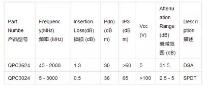
Qorvo announced that it will expand its CATV product portfolio and launch two new control products specifically designed for DOCSIS 3.1 wired network-Q ...
Fiber fusion loss is mainly composed of the transmission loss of the fiber itself and the fusion loss at the fiber fusion splice. Due to the quality of the optical fiber connection ...
The digital multi-point distribution system combines network technologies such as 2G, 3G, and WLAN to maximize the common access of multiple network systems. The system is connected by multimode source ...
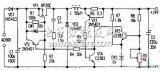
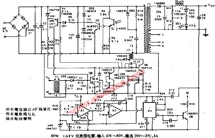
The power supply system of cable TV is AC 60V centralized power supply. CATV amplifier power supply usually use two kinds of power transformer step-down or isolated switching power supply ...
Advanced semiconductor solutions provider Renesas Electronics (Renesas Electronics) has announced that it is suitable for 1GHz wired ...
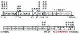
This frequency-splitting configuration is suitable for large-scale integrated service networks, and the upstream channel is extended by 35 MHz from 5-30 MHz, which provides the possibility of developing interactive services; ...
CATV image quality subjective evaluation table. The subjective evaluation of the user-side image quality is based on the five-level damage standard, which should refer to the international GB7401 No. 4 ...
The MAX3518 is an integrated CATV upstream amplifier IC designed to meet the requirements of DOCSIS 3.0, with a power consumption of only 1.2 ...
What is a cable (CATV) data network? In some countries, the cable TV industry has become an upgraded CATV (cable TV) network ...
What is CATV (Cable TeleVision) English abbreviation: CATV (Cab ...
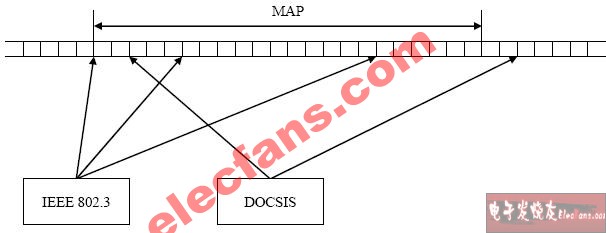
1 The principle of CATV network upstream transmission The upstream transmission of CATV network is a multipoint to single point transmission [1], we must consider shared media ...
Summary of conversion of dBm, dBmV and dBµV in CATV: Cable TV system is generally based on 75Ω interface, but absolutely ...

CATV MAX3509 + 68dBmV cable telephone upstream communication plan: To increase the MAX3509 cable upstream amplification ...
CATV upstream amplifier selection guide summary: This selection guide provides MAX3503, MAX3505, MAX3507, ...
MAX3505 application circuit (CATV upstream amplifier) ​​typical working circuit
'+ data.data.username +' '; dom + ='
Shareconn development co.,Ltd have more than 15 years experience in wire harness. we always manufacture automotive wireharness, Sensor Wire Harness, LVDS wire harness and Electronic Wire Harness, according to IPC 620 standard.
Our factory can offer FAI and Environmental protection certificates.
We inspect all wire harness 100% percent before we ship out. We ship all goods with OQC inspection reports and COC reports.
Our factory is qualified with ISO9001:2008, ISO13485:2003 and TS16949:2009 certificates, equipped with high-end automatic production equipment, like automatic crimping machines, automatic wire cutting and crimping machines, automatic crimping and tinned plate machines, etc. 

Wire Harness Assemblies,Wiring Assembly,Wire Harness Assembly,Custom Wire Harness Assemblies
Shareconn Development CO.,LTD , http://www.share-conn.com