Input range 0.9V-5.5V
The output can be fixed at 5V or 3.3V, or between 2V and 5.5V.
DC-DC efficiency can reach 94% at 5V output of 5V
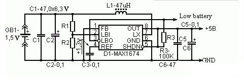
Figure 1 Input 1.5v liter 5v booster with MAX1674
Booster 1.5v liter 5v circuit diagram (2)Providing an output to a 2.5V to 3.0V circuit will yield approximately 70% efficiency with an output current of 20mA.
The 1.5V liter 9V power supply circuit diagram is shown in the drawing. This circuit is a batch oscillation boost circuit. BG1 and L1, L2, C1, etc. constitute an oscillator. BG1 is an oscillating tube and operates in a switching state. L1 and C1 are oscillation feedback elements. L2 is an oscillating energy storage winding. For convenience, the circuit also designed an automatic electronic switch composed of BG3. When the base of BG3 has no load, there is no base current, BG3, BG2, BG1 are all cut off, the whole circuit stops working, and no power is consumed. Therefore, this circuit does not require a separate power switch.
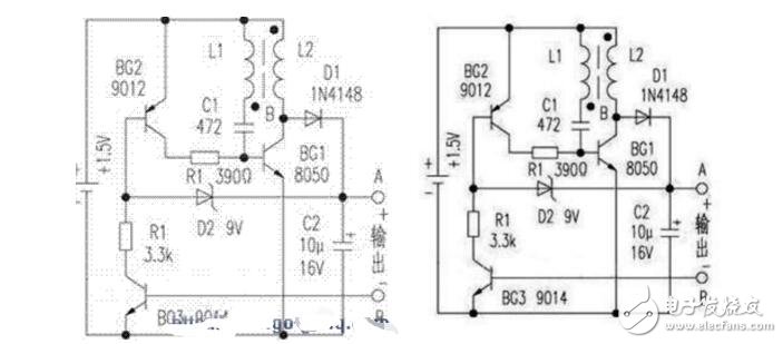
When the two points of A and B are connected to the load, BG3 is turned on, and BG2 is also turned on. The load supplies the base current to BG1, and BG1 is turned on. The energy flows in from the power supply and is stored in L2. At this time, the collector voltage of BG1 is very low, D1 is cut off, and the load is supplied by the residual voltage of C2. When BG1 is turned off, the current in L2 cannot be abruptly changed, and it will produce a higher counter-electromotive force, which is rectified by D1 and output. When the output voltage is higher than the regulation value of D2, the b and e junctions of BG2 tend to be reversed, and the base current of BG1 will decrease, forcing the oscillation to weaken, and the output voltage will also drop to automatically output the voltage. Control is near the regulation value of D2.
Component selection and production debugging:BG1 selects NPN type silicon tubes with reduced saturation voltage, such as 9013, 8050, etc., and requires ICM"300mA, β"200. BG2 can use PNP silicon tubes such as 9012 and 9015, and BG3 uses NPN type tubes such as 9014. The smaller the penetration current is, the better. L1 and L2 are wound on a 高频8MM high-frequency magnetic ring (detached from an old electronic ballast or energy-saving lamp) with a MM0.1MM enameled wire. L1 is 6åŒL2 is 36åŒ.
I use this circuit to supply power to the DT890A digital multimeter. The measured working current is: buzzer and capacitor 20uF, 2uF block is below 45mA, other gears are below 25mA. When the battery voltage drops to 0.9V, in addition to the buzzer block that consumes a large current, the capacitors 20uF and 2uF block have a power shortage display, and the remaining gears have no power shortage display. The circuit is simple to manufacture, stable in performance, economical and practical. No need to debug, as long as the wiring is correct, it can work normally.
Digital Multimeters If a 1.5V battery is used to replace a 9V stacked battery with a boost, it is usually necessary to install a separate power switch. Inconvenience to production and use. The circuit described in this article controls the start or stop by detecting the presence or absence of the digital multimeter's operating current. Therefore, as long as the power line is connected to the output of the booster circuit, the digital multimeter power switch can be used.
3000 puffs disposable vape pen are so convenient, portable, and small volume, you just need to take them
out of your pocket and take a puff, feel the cloud of smoke, and the fragrance of fruit surrounding you. It's so great.
We are China's leading manufacturer and supplier of disposable vape puff bars, disposable vape 3000 puffs,disposable vape pens 3000 puffs,
big bar vape 3000 puffs,3000 puff vape pen, and e-cigarette kit, and we specialize in Disposable Vapes, e-cigarette vape pens, e-cigarette kits, etc.
disposable vape 3000 puffs,disposable vape pens 3000 puffs,big bar vape 3000 puffs,3000 puff vape pen,3000 puffs vape bar
Ningbo Autrends International Trade Co.,Ltd. , https://www.vapee-cigarettes.com