The growth of the hybrid electric vehicle (HEV) market is highly dependent on the energy consumption per gallon/mile and the benefits of each additional coin and the reliability of the hybrid system. Consumers compare hybrid cars to standard cars and expect to have at least the same performance and reliability at a lower overall cost of ownership. The added cost of a hybrid car must be rewarded by saving fuel and maintenance costs during ownership.
This article refers to the address: http://
The power modules used in inverters and dc-dc converters in HEVs and the power devices therein are the primary performance, reliability and cost drivers. Efficiency, power density and specific power are some of the key performance indicators. The most important reliability specifications are thermal cycling and power cycling.
Hybrid car classification
In a hybrid vehicle drive system, one or several motors are used with the combustion engine. Hybrid cars can be classified according to the degree of mixing and system architecture. The degree of mixing that can be divided into micro, mild, and full stages determines the function performed by the motor. This classification also determines the power level required and the preferred system architecture.
Serial, parallel, and power allocation are the most common architectures. For a particular vehicle, the choice of blending level and system architecture depends primarily on the required function, vehicle size, length of travel, and set fuel economy metrics. The power electronics content of each hybrid system varies, depending on the function, power requirements, and architecture.
When only the start-stop function is required (such as a wagon), it is common to replace the parallel micro-mixing of the starter and alternator with an integrated starter/alternator system. In these systems, the voltage and power levels are relatively low, and the fuel consumption improvement is around 10%.
In addition to the start-stop function, a mild hybrid system boosts/assisted engine power when needed, and it also extracts energy from regenerative braking, which increases fuel consumption to around 15%. Increased functionality requires higher power consumption, so high voltage devices (80 V to 600 V) are used.
If the vehicle is operated in full electronic mode, a fully hybrid system with high voltage and high current capability is required. Depending on the application, a fully hybrid system can have a serial, parallel, and power distribution architecture that reduces fuel consumption by 35%.
Challenges for power electronics in HEV systems
Power electronics in HEV systems need to efficiently transfer energy from dc to ac (battery to motor), from ac to dc (generator to battery), and from dc to dc (for boost converters, from low to low The battery voltage is high to the inverter input voltage; for buck converters it is from high voltage battery to low voltage battery). Since high voltage and large current are to be switched in this energy conversion, power device technology with the lowest loss is required. For lower system voltages and currents, MOSFET technology has better power density than IGBTs and they are used in micro-hybrid applications. For mild hybrid applications, IGBTs are the device of choice when the system voltage is above 120V. For full hybrid applications, 600V to 1200V IGBTs are the only devices used.
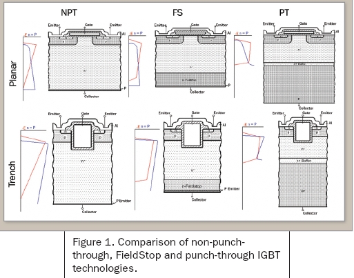
In general, traditional NPT IGBTs have a balance between conduction loss and switching loss characteristics. If the conduction loss is reduced, the switching loss is increased. Infineon's channel FieldStop IGBTs and associated EmCon diode technology reduce turn-on and switching losses while increasing chip current density compared to conventional devices. Lower losses are obtained by using a field stop layer that reduces device thickness and reduces voltage drop across the device. Figure 1 shows the cross-section of different IGBT technologies used in planar and trench devices. In addition, Field-Stop devices can operate continuously at junction temperatures of 150 °C (up to 175 °C), which enhances chip current density and makes it easier to use higher cooling temperatures.
Power modules embedded in a convenient package can withstand extreme temperature conditions, vibration and other harsh environmental conditions. In addition to temperature changes caused by device operation, environmental temperature variations and vibrations generated in the vehicle pose reliability challenges. The expected life of a power module in hybrid automotive applications is 15 years / 150,000 miles, so the module should be designed to have the desired reliability. For example, in some cases, higher device performance can adversely affect the stability of the module. From a device technology perspective, some power devices can operate at high junction temperatures, but this higher junction temperature will result in higher temperatures on the wire bond interface, reducing the stability of the module's power cycle. Therefore, a comprehensive set of device and package specifications is needed to optimize performance, reliability and cost.
Hybrid vehicle power semiconductor module
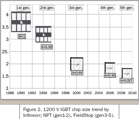
Applications require power modules with high current densities, which means smaller volumes per unit current capacity. The smaller the device, the smaller the underlying layer that is included in it, resulting in a module that is small but has a higher power density. Figure 2 shows the reduction in the 1200V device volume expected by Infineon. Obviously, the FieldStop device significantly reduces the size compared to NPT devices.
Package design and interconnect technology have a large impact on the parasitic inductance of the modules, and they can also be used to improve power density. In addition, the materials chosen will also have an impact on performance and reliability. For example, the cost of a silicon nitride underlayer is much higher than the cost of an alumina underlayer, but the thermal performance of the former is significantly better than the latter. Also, expensive aluminum silicon carbide substrates have much higher thermal cycling reliability than inexpensive copper substrates.
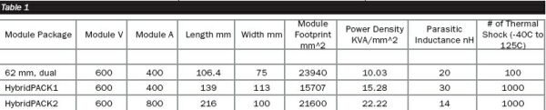
When designing a power module for an HEV, it is important to identify key obstacles at the beginning of the design. Appropriate device technology, underlying layout, and packaging techniques are required to meet performance, reliability, and cost targets. Table 1 shows the performance and reliability of the three modules: standard half-bridge 62mm modules for industrial variable speed drives, six-pack HybridPACK1 modules for light mixing (Figure 3) and a six-pack HybridPACK2 module for full mixing.
The same 600V channel FieldStop device technology is used in all three modules, but the packaging technology used is different. The 62mm and HybridPACK1 modules implement a device current of 400A (two 200A IGBTs and two 200A diodes per switch), while the HybridPACK2 module has a current of 800A (four 200A IGBTs and four 200A diodes per switch). The packaging techniques for the power and signal thermal connections of the 62 mm, HybridPACK1 and HybridPACK2 modules are: soldering, wire bonding and ultrasonic welding. The power density of the HybridPACK1 module has been increased by 50% over the 62mm module through layout improvements and wire-bonded power and signal thermal connections. Although parasitic inductance is increased by 50%, this is not a major issue for 600V devices because the worst system voltage conditions are below 200V in mild hybrid applications.
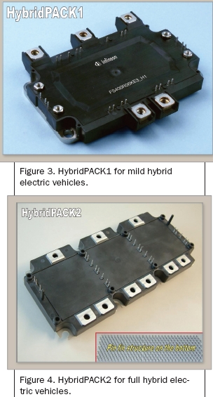
With an innovative ultrasonic welding process and improved layout, the power density of the HybridPACK2 module has increased by more than 120%. Multiple wire connections and space allocated for moving the bonding tool make the wire bond thermal connection take up space in the package; ultrasonic welding eliminates this space and is faster than the wire bonding process. In addition, the current binding capability of wire bonding is limited. Since the thick copper terminal is fused with the bottom layer during ultrasonic welding, the current carrying capacity of the ultrasonic welding is not limited. The more compact package also significantly reduces the self-inductance of the HybridPACK2 package. For full hybrid applications, low parasitic sensing is important because the system voltage is higher than 400V and large currents produce large dI/dt.
The thermal impedance of the module depends mainly on the chip area occupied by each switch, the material stack of the module, and the underlying layout. The material stacking characteristics directly affect the thermal impedance of the module, while the layout increases the cross-conduction portion. In the 62mm and HybridPACK1 modules, a flat copper base layer is used, while the HybridPACK2 uses an integrated pin-finned copper base layer. For modules with a flat base layer, the thermal impedance of the thermal grease and the thermal layer are added together to obtain a thermal impedance from junction to environment. The thermal impedance performance of the HybridPACK2 module is significantly improved by removing the thermal grease layer and soldering the underlying layer directly to the pin fin tube substrate.
A mismatch in the thermal expansion of adjacent materials within the module will cause pressure deformation at the joint and eventually lead to failure. The maximum pressure is generated on the copper substrate to be soldered to the underlying solder joint. To enhance reliability, module manufacturers have traditionally used a combination of an aluminum nitride underlayer and an aluminum silicon carbide substrate, which adds significant cost. To replace expensive aluminum-silicon carbides, Infineon has developed HybridPACK1 and HybridPACK2 modules with copper substrates and a modified alumina substrate. This combination of materials meets the reliability target requirements, but at a much lower cost. The reliability goal of the car is 1000 cycles from -40 °C to 125 °C.
in conclusion
The performance, reliability and cost of power modules are the main drivers for the growth of the HEV market. To reduce cost, the power density and junction temperature of the devices in the power module need to be reduced. Infineon's channel FieldStop IGBTs and EmCon are such devices that increase junction temperature while reducing conduction and switching losses. The power density of the module can be significantly improved by using efficient power devices and ultrasonic welding techniques; likewise, the integrated pinhole tube base layer improves thermal performance. The improved alumina underlayer and copper substrate approach provides the highest reliability for HybridPACK modules at low cost. For full hybrid applications, the HybridPACK2 is an excellent module that offers high power density, low self-inductance, low thermal resistance, and optimum reliability and lowest cost.
REFERENCES
1. McKinsey & Company, “Drive — The future of Automotive Power,†2006.
2.R. Amro et al, “Power Cycling at High Temperature Swings of Modules with Low Temperature Joining Technique,†​​ISPSD 2006, Naples.
3. T. Laska et al, “The Field Stop IGBT (FS IGBT) — A New Power Device Concept with a Great Improvement Potential,†Proceedings of the 12th ISPSD, pp. 355-358, 2000.
4.P. Kanschat et al, “600V IGBT3: A Detailed Analysis of Outstanding Static and Dynamic Properties,†Proc. PCIM Europe, pp. 436-441, 2004.
5.A. Kawahashi et al, “A New-Generation Hybrid Electric Vehicle and its Supporting Power Semiconductor Devices,†Proceedings of 16th ISPSD, pp. 23-29, 2004.
We also equipped with a series of numerical control conveyor systems of flattening, cutting, folding and auto-welding, we could manufacture all kinds of steel poles and steel towers, for example, 11m Steel Pole.
3-12M Steel Poles,Steel Light Poles,Galvanised Steel Poles,Steel Street Light Poles,11M Steel Pole
YIXING FUTAO METAL STRUCTURAL UNIT CO.,LTD( YIXING HONGSHENGYUAN ELECTRIC POWER FACILITIES CO.,LTD.) , https://www.chinasteelpole.com