1 Introduction
The flue gas released by the industrial combustion process is the source of air pollution in modern cities. The flue gas detection is a necessary item in the atmospheric environment detection. It is the basic means to determine the key pollution sources and to detect and control the pollution sources. In order to control the combustion air ratio in the combustion process, improve combustion efficiency, save energy, and reduce air pollution, it is necessary to reliably measure the content of various gases in the flue gas. This article introduces an intelligent instrument monitoring platform based on Intel microcontroller for flue gas analysis.
2 The hardware structure design of the monitoring platform
The hardware configuration should be selected in each module for different combinations of analysis detectors. For example, when the platform is used for two-component analysis, only two operating circuits and signal circuits are connected, and the other two are not connected. Due to the hardware With the independent characteristics of the module and the system parameter setting function of the software, the system can work normally, and the unconnected loop does not affect the working loop. The hardware structure of the monitoring platform is shown in Figure 1.
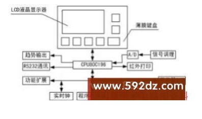
Figure 1 Hardware structure diagram of the monitoring platform
3 Detailed hardware design of each functional module
3.1 Selection of single-chip microcomputer and design of memory module
The core of the intelligent instrument is a single-chip microcomputer, whose performance has an important influence on the performance of the entire embedded system. When choosing, it is necessary to take into account the background of industrial applications, the function has a certain degree of advancement and high reliability, and it must also meet the requirements of the multi-variety, small-batch functional platform of analytical instruments, and it is easy to develop, transplant and update. To this end, Intel’s 80C196kc chip is determined as the information processing unit of the analytical instrument to construct a portable instrument monitoring platform.
What this monitoring platform chooses is the 32k byte flash memory 29C256 produced by ATMEL company, the working voltage is 5v, once the working voltage is lower than 3.8V, the programming function is forbidden. It not only has the speed and ease of erasing and writing of SRAM, but also can maintain data and online writability after power failure like EEPROM. It has read and write functions and can save data when power is off. The hardware design method is shown as in Fig. 2. The P4 port of 80C196kc is used as the high bit of the address, the P3 port is used as the low bit of the address and the 8-bit data line for time sharing, and the 74LS373 is used for the low bit address latch.
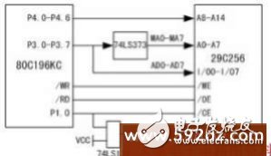
Figure 2 Memory hardware circuit design
3.2 A/D sampling and data processing module
The 80C196kc on-chip A/D module has a total of 8 sampling channels with an accuracy of 10 bits (of which the reliable accuracy is 8 bits). This monitoring platform has used two of them: one of them is used for thermocouple temperature measurement, if the thermocouple channel is detected If the voltage is abnormal, the alarm will indicate that the thermocouple is open; the other is used to detect the battery voltage of the instrument, and the detection result is displayed on the liquid crystal display, so that the user can know the battery level at any time, so as to prevent the sensor from being damaged by the low voltage; the remaining six are standby. The off-chip is the 12-bit A/D sampling chip produced by MAXIM Company-MAX197, which is responsible for completing the signal sampling of 6 different sensors and the detection of ambient temperature and flue gas temperature. The chip is a 28-pin dual in-line package, with a working voltage of 5V, 8 analog input ports, and a conversion time of 6μS.
Since the electrical signal converted by the sensor of the analysis instrument is 0~1V, it is obviously not possible to use the internal reference voltage mode for sampling, so the system selects the external reference voltage mode. But the author found in actual use that the external reference voltage cannot be too low. Experiments have shown that when the external reference is lower than 1V, when the input analog quantity is below 90 mV, the sampling result is obviously inaccurate, there are very serious nonlinearities, and even obvious dead zones. Therefore, the monitoring platform adds an amplifier between the sensor and the A/D sampling chip to amplify the signal transmitted from the sensor to the A/D sampling chip to 0~2V. The external reference voltage VREF=2/1.2207=1.6384 can be known by calculation. V. Facts have proved that this method has played a good role, and the A/D sampling chip has played a good performance, which meets the requirements of the monitoring platform.
3.3 LCD liquid crystal display module
The LCD liquid crystal display is an important window of the man-machine interface and one of the characteristics of this monitoring platform. All human-machine interaction functions of this platform are completed through the LCD and the keyboard. The keyboard is designed with 2×4 touch buttons, occupying 6 I/O ports of the CPU, and one of the buttons is connected to the instrument's startup circuit and becomes the startup key of the analytical instrument. The liquid crystal display adopts a 240×128 dot matrix large screen wide viewing angle liquid crystal display (LCD). There are 21 external interface pins of the display module, of which Pin18 is the font selection pin for displaying characters, and it is displayed when connected to high level. The font of is 8×6, and the font displayed when connected to low level is 8×8. The LCD screen has a built-in driver T6963C and peripheral circuits, and has a hardware initialization function.
Pin4 of LCD is the contrast adjustment pin of the display area, and the access voltage can be adjusted between -6V and 18V. This monitoring platform selects MAX749 chip produced by MAXIM company in 8-pin dual-in-line package to provide the oscillating voltage of the brightness adjustment of the LCD screen. This chip is specially designed for LCD contrast voltage adjustment, and its output voltage has good adjustability, which can be realized by three methods: digital control, potential adjustment, and PWM control. The working circuit is shown in Figure 3.
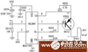
Figure 3 MAX749 working circuit design
3.4 Infrared printing and serial communication module
According to the infrared printing protocol, the hardware part of the printing module is mainly realized by the infrared physical layer including the infrared transceiver and the codec hardware circuit. The physical layer encoding and decoding uses HP's infrared 3/16 encoding and decoding chip-hp-7001. This chip uses 1.63μs or 3/16 pulse mode to send and receive signals, and the baud rate can be programmed. The infrared transceiver uses Agilent's hsdl-3610, which is fully compatible with IrDA 1.1, the highest transmission rate can reach 4Mbps, the connection distance is greater than 1.5 meters and the power consumption is less. Considering that the serial interface of the single-chip 80C196kc needs to be used for data communication, HSO and HSI are used to realize infrared printing-like serial data output and input. Because the receiving and sending pins of 80C196kc and hp7001 are all TTL levels, they can be directly connected without level conversion chips such as MAX232. Considering that 9600bps is the basic baud rate of the infrared communication protocol, so 80C196kc and hp-7001 and hsdl-3610 all use 9600bps for communication.
The serial port communication uses the serial data interface of 80C196kc, adopts the RS-232 way, realizes the level conversion of the serial signal by MAX232. It adopts 8 data bits, one stop bit, and no parity bit. Three baud rates of 4800, 9600 and 19200 are provided for users to choose, so as to meet the needs of computer communication. When communicating, only need to connect the instrument and the computer with a serial cable, and run the corresponding program to complete the data transmission. This communication only transmits the historical sampling data that has been stored in the flash. Up to 40 sets of data can be transmitted at a time. Each set of data includes all sampling parameters, calculation parameters and system parameters (such as date and time, fuel type, etc.) during data storage.
3.5 Power startup and conversion module
As portable analytical instruments use batteries for power supply, it is extremely important to reduce the overall current and standby current, and reduce losses. The working voltage of the sensor part is 12V, and the monolithic system uses 5V power supply. Therefore, the control platform uses a DC-AC-DC conversion module to complete the power conversion. The XR031 voltage conversion module is selected, and its conversion efficiency reaches 80%. The start-up circuit uses CMOS chips to form a flip-flop circuit with Schmidt shaping, and the start key on the instrument keyboard controls the opening and closing. The battery still supplies power to this part of the circuit in the shutdown state, and its current is extremely small, about 4 to 8 microamps. In the working state, the internal A/D sampling module of the CPU performs voltage detection on it. When the voltage is lower than the setting, the output is set. The port is an effective level, and the level is generated by the differential circuit to generate a +12V sharp pulse to trigger the flip-flop circuit to flip to achieve forced shutdown. When the monitoring system is working normally, the power consumption current is 50-60mA (LCD backlight is off, excluding pump current), and the maximum current of the whole machine is 140mA (LCD backlight is on). The hardware design of power conversion and startup is shown in Figure 4.
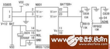
Figure 4 Power startup and conversion circuit
3.6 Clock module
This design uses a real-time clock chip DS12C887, which is a commonly used clock chip in microcomputers. The chip is an integrated component in a 24-pin dual in-line package. The component contains a quartz crystal, a lithium battery, a real-time clock, a calendar clock, an alarm clock, and 128 bytes of RAM, of which 15 bytes are used as the real clock The remaining 113 bytes of the control register can be used as ordinary RAM, and the data can also not be lost for ten years. The year, month, day, hour, minute, and second information of the DS12C887 are all stored in the internal registers.
4 Software design of the monitoring platform
The software system of the monitoring platform adopts C program design, uses C96 compiler, and the version is version 5.3. Although the compiler occupies more program space than assembly language compiler, the program development cycle is greatly reduced, debugging efficiency and readability are significantly better than assembly language, and the original program can be transplanted to other types of chips more conveniently, which is convenient for products Update.
The monitoring platform software system is a multi-task real-time operating system, which is mainly divided into five functional modules: man-machine interface, serial communication, data processing, infrared printing, and operation control. The software structure block diagram is shown in Figure 5. Due to the modular design of the system, each module forms its own system and can be independently debugged, which facilitates system integration and facilitates the formation of monitoring programs for other analytical instruments. The software system supports both Chinese and English versions of the interface for users to choose from. The LCD display page reaches more than 60, the font library has more than 250 Chinese characters, and the compiled program code is about 52Kb.
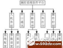
Figure 5 Software system design
The entire software system uses the Super-Loops structure. The application program is an infinite loop. In the loop, the corresponding function is called to complete the specified operation. The program checks each input condition of the system in turn, and performs corresponding processing once the condition is established. , This part can be regarded as task-level processing. The interrupt service routine processes asynchronous events, and this part is regarded as interrupt-level processing. This system includes modules such as A/D sampling, HSO real-time interrupt, HSO event interrupt, serial communication, etc. To ensure real-time performance, the interrupt service program only includes logo processing, and its implicit functions such as sampling value filtering and HSO event queuing are all performed by Task-level processing. Real-time multitasking is classified and processed according to task level, and time event processing modules are included in each interface processing module to ensure timing event processing.
Innovations of the author of this article:
Powerful CPU and good modularity make the research of this monitoring platform provide a design platform with ARC function for intelligent analysis instruments. Through the choice of software and hardware modules, it can basically realize a variety of combined analyzers with different requirements. The system improves the automation level of the analytical instrument itself, and the automatic calibration and diagnosis of the analytical instrument.
2.54Mm Pin Header Connector,2.54Mm Vertical Type Connector,2.54Mm Pin Header Vertical Type Connectors,2.54Mm Right Angle Type Connector
Shenzhen CGE Electronics Co.,Ltd , https://www.cgeconnector.com