The DCS control system of a chemical plant is composed of system software, hardware, and on-site instruments. Any problem in any one of these links will result in the failure of some of the functions of the system or the failure of the control system. In severe cases, the production plant will stop. How to solve when DCS fails? And look at the following content.
Control station section
The main control card fault light flashes. When the system configuration, communication and other aspects of the failure, the main control card will self-diagnosis of these failures, at the same time with different flashing fault light to indicate different symptoms.
All cage fault lights in one cage are flashing. This occurs when the address of the data forwarding card is incorrect, data forwarding card is faulty, the data forwarding card configuration information is incorrect, the cage's SBUS line is in communication failure, or the power supply to the cage is low-voltage faulted. Data for the entire cage is not refreshed or becomes zero. The method of judging the fault point is to use the "replacement method". Replace the data forwarding card and make it work. Observe whether the system is back to normal (be careful not to set the address of the data forwarding card during the replacement). If the system is still abnormal , you need to contact the supplier.
A card fault light flashes or all data on the card is zero. The possible reason is that the configuration information is wrong, the card is in standby status, the redundant terminal cable is not connected, the card itself is faulty, and there is no configuration information in the slot. When other possibilities are suspected and the card itself fails, the "replacement method" can be used.
Some channel data is abnormal. In this case, the maintenance engineer needs to accurately determine whether the fault point is on the system side or the field side. The simple method is to disconnect the signal line, use a multimeter and other measurement tools to check whether the field side signal is normal or send the system a standard signal to see if the monitor screen is normal. If the fault point is initially determined to be on the system side, then the location of the fault point is determined in order of channel, card, cage, and control station from small to large. For various types of control station cards, the reasons for the data failure or distortion of a channel are various. For current input, it is necessary to determine whether the card is working, whether the configuration is correct, the power distribution mode jumper, and the polarity of the signal line is correct. Maintenance personnel need to correctly determine the location of the fault and perform corresponding processing.
Operator station section
Host failure
The operator station is an industrial PC and its basic structure is not fundamentally different from an ordinary desktop computer. When a PC fails, first use the plug method, replacement method, and comparison method to determine which component in the PC is faulty, and then replace the faulty component or replace the slot in a targeted manner. (Replace PC components generally. By the engineering and technical personnel in the field guidance).
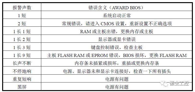
In order to avoid blindly replacing components, the fault can be determined based on the number of alarms when the PC starts up.
Display failure
When the display does not display properly and the IPC is removed, check the display's button settings.
Determine the position of the "D-SUB/BNC" button on the front of the monitor: If the signal cable on the rear of the monitor is connected via the 15-pin D-type interface cable, the button is placed in the "D-SUB" position; if the signal line on the back of the monitor is connected through the BNC type Interface cable, this button is placed in the "BNC" position.
If the display back signal line connection is through the BNC type interface cable, determine the synchronization signal switch "Sync.Switch" position: If you use the green synchronization signal (3BNC) mode, the switch is set to "SOG" position; if separated by H, V In the synchronous signal (5BNC) or H+V hybrid synchronous signal (4BNC) mode, the switch is set to the "H/V" position.
When the color of the monitor is not pure, press the “degauss†button on the front of the monitor to eliminate electromagnetic interference.
If the display button setting is correct and the display is still abnormal, replace the standby display or office display temporarily with the display and contact the supplier for display maintenance.
In the rectifier circuit; the use of diodes in series can increase the back pressure withstand value (usually the sum of the back pressure of all diodes, but it is best to use diodes of the same specification).
In the voltage stabilization circuit; the series connection of the diode is equal to the sum of the voltage stabilization value of the diode. The use of diodes in parallel is theoretically the sum of rated currents, but considering that it is impossible to be absolutely symmetrical, they can only be used below 80% of the total.
TVS transient suppressor diodes work in the same way as regulator diodes, but there are structural differences.The biggest difference is that the PN junction area composed of the general regulator diode is very small, it can withstand the reverse current is small.
Transient Voltage Suppressor,Transient Voltage Suppressor Diode,Series diode
Changzhou Changyuan Electronic Co., Ltd. , https://www.cydiode.com