A signal whose signal changes continuously in both time and value is called an analog signal. Electronic devices that transmit analog signals are called analog electronics.
The main contents of analog electronics include: common semiconductor devices, basic amplifier circuits, multi-stage amplifier circuits, integrated operational amplifier circuits, frequency response of amplifier circuits, feedback in amplifier circuits, signal calculation and processing, waveform generation and signal Conversion, power amplifier circuit, DC power supply, analog electronic circuit read the picture.
This article mainly summarizes 10 basic analog electronic circuits, and hopes to help you learn.
XI. Differential amplifier circuit
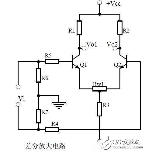
1, the role of the various components of the circuit, the use of the circuit, the characteristics of the circuit.
2. Analysis of the working principle of the circuit. How to amplify the differential mode signal and suppress the common mode signal.
3. Single-ended input and double-ended input of the circuit, single-ended output and double-ended output working mode.
Twelve, FET amplification circuit
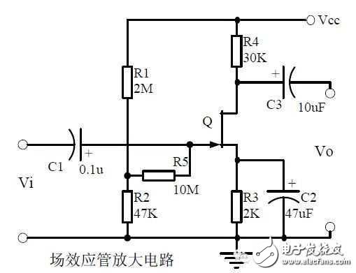
1. Classification, characteristics, structure, transfer characteristics and output characteristic curves of FETs.
2. The characteristics of the field effect amplification circuit.
3. Application of field effect amplification circuit.
Thirteen, frequency selective (bandpass) amplifier circuit
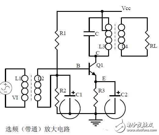
1, the role of each component:
Features of the frequency selective amplifier circuit:
The role of the circuit:
2. Calculation of characteristic frequency:
Selection of frequency selection component parameters:
3. Frequency-frequency characteristic curve:
Fourteen, operational amplifier circuit
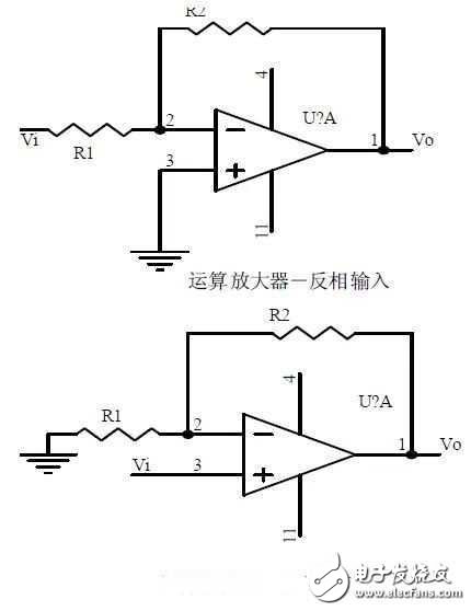
1. The concept of an ideal operational amplifier:
Virtual short circuit at the input of the op amp:
Virtual break at the input of the op amp:
2. The main purpose of the op amp circuit of the inverting input mode:
The phase relationship between the input voltage and the output voltage signal is:
3. The gain expressions in the in-phase input mode are:
The input impedances are:
The output impedances are:
Electric Two And Three Wheelers Battery
Electric Two And Three Wheelers Battery,Electric Motorcycle Lifepo4 Battery,Lifepo4 Battery For 2 Wheeler,23Ah Lifepo4 Battery For 2 Wheeler
JIANGMEN RONDA LITHIUM BATTERY CO., LTD. , https://www.ronda-battery.com