RS485 disadvantages:
RS485 bus is a kind of conventional communication bus. It can't do automatic arbitration of bus, that is, it can't send data at the same time to avoid bus competition. Therefore, the communication efficiency of the whole system is inevitable, and the data redundancy is large. High-demand applications do not apply to the RS485 bus. At the same time, since there is usually only one host on the RS485 bus, this bus mode is a typical centralized - distributed control system. Once the host fails, the communication of the entire system is limited to the 瘫痪 state, so doing online backup of the host is an important measure.
** Typical circuit for traditional opto-isolation:

VDD and +5V1 ( VCC485 ) are two sets of power sources that are not shared, and are generally implemented by isolated DC-DC . Isolation transmission of signals is achieved by optocoupler isolation. The ISL3152EIBZ and the MCU system are not shared. The complete isolation effectively suppresses the generation of high common-mode voltage, greatly reduces the damage rate of 485 , and improves system stability. However, there are also shortcomings such as excessive circuit size, cumbersome circuits, excessive discrete devices, and limited transmission rate by optoelectronic devices, which also have a certain impact on the stability of the entire system.
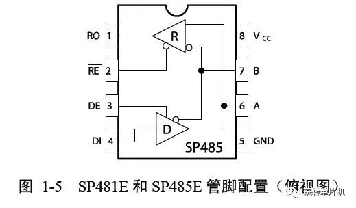
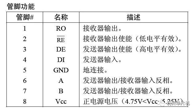
***RXD1: serial port receiver
***TXD1: serial port transmission end
***TRE1: is the control bit: control whether to send or receive data;
When TRE1=1 (high level), the optocoupler circuit 121 is turned off, /RE=1 ( invalid ) , DE=1 ( valid ) , that is, data is transmitted;
When TRE=0 ( low level ) , the optocoupler circuit is turned on, /RE=0 ( valid ) , that is, receiving data, DE=0 ( invalid ) ;
/RE: 485 receiver
DE: 485 sender
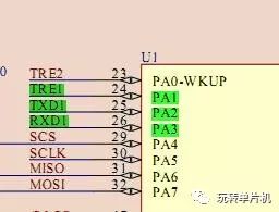
The first step is to configure the serial port transmit and receive pins and the 485 control pin.
Because the RXD1 pin receives external data relative to the STM32 chip, it is set as an input;
The TXD1 pin is externally transmitted with respect to the STM32 chip, so it is set as an output;
The TRE1 pin is a high-low command that sends " 1 " or " 0 " to the outside, so it is set as an output.
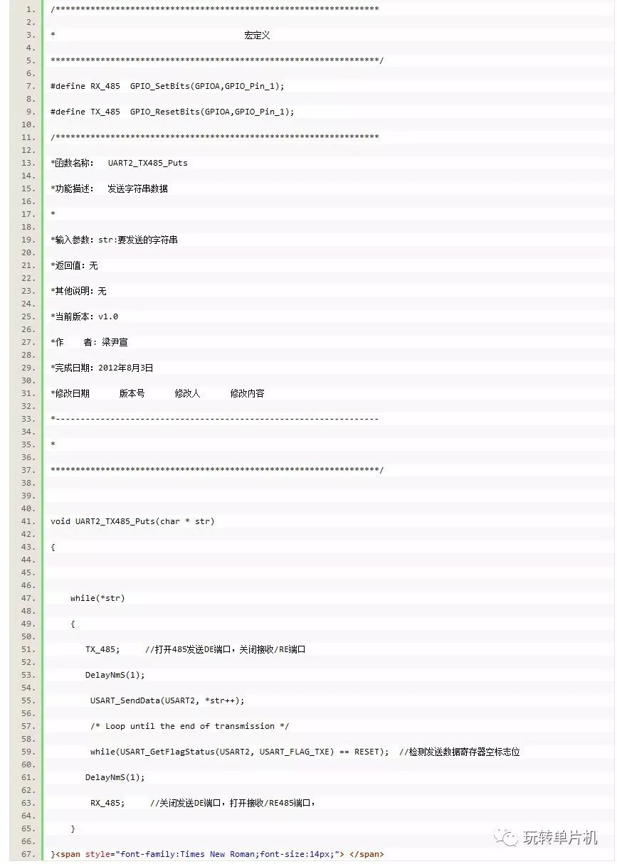
Step 2: Send data
The things to note here are:
/ * The CPU small defects: Serial configured, if the Send direct, the first byte is not sent out
Statements following two methods to solve the problem of a byte can not send out the right * /
Method 1: USART_ClearFlag(USART3, USART_FLAG_TC); /* Clear the completion flag, Transmission Complete flag */
Method 2: /* Get the serial port 1 status flag */
USART_GetITStatus(USART1, USART_FLAG_TC);
The reason for garbled when powering up:
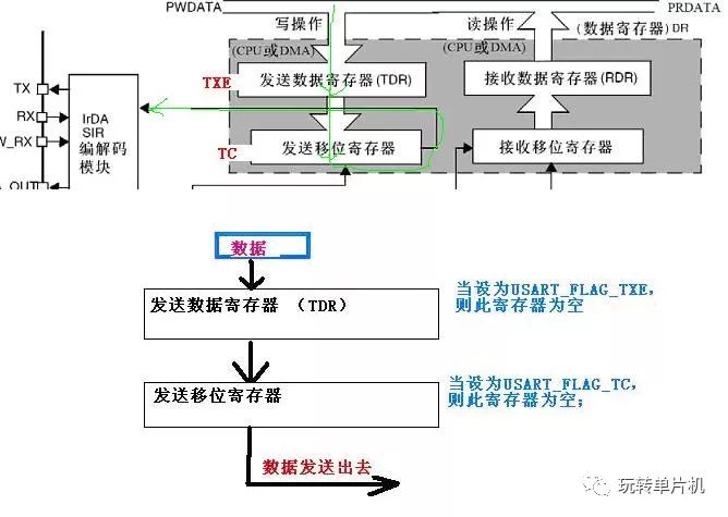
While(USART_GetFlagStatus(USART2, USART_FLAG_TXE) == RESET); // USART_FLAG_TXE--- Detect Transmit Data Register Empty Flag
If USART_FLAG_TC--- send completion flag
(1) When set to USART_FLAG_TXE--- detect transmit data register empty flag bit - empty, but the transmit shift register is not empty, the data has not been completely sent out, and some data is written in, so it will Prone to garbled;
(2) When the set USART_FLAG_TC- detected transmission complete flag - is empty, i.e., the transmit shift register is empty, only the real data sent, data is written so at this time there does not come distortion occurs
STM32 data transmission has two interrupt flags, one is the transmit data register empty flag, and the other is the send completion flag. Both flags can cause an interruption .
To send a packet in an interrupted manner, the process looks like this:
1. Set the direction of RS485 to send, enable the transmit register empty interrupt, and enable the serial port interrupt when enabled.
2. The serial port interrupt reads the serial port status and fills a data to the transmit data register . The hardware automatically clears the transmit data register empty flag , and the serial data transmission starts.
3. After the serial port sends out a data, the transmit data register becomes empty, and then enters the interrupt, and continues to fill the next data until the last data is filled , enabling the serial port.
The transmission is interrupted.
4. After the last data is sent , enter the interrupt again , clear the send data register empty flag, clear the send completed interrupt flag, clear the two interrupt flags.
The enable bit sets the direction of RS485 for reception .
In the communication of the 485 chip, in particular, pay attention to the software programming of the 485 control terminal DE . In order to work reliably, it is necessary to make appropriate delays when switching the 485 bus state, and then send and receive data. The specific approach is in the data transmission state, Â Â Â First set the control terminal to " 1 ", delay the time of about 1ms , send valid data, delay 1ms after the end of one packet of data transmission, set the control terminal to " 0 ", this will make the bus switch state. When there is a stable working process.
Clevis fitting,High Quality Overhead Line Fittings,Link Fitting,Parallel Clevises,Forged Ground Rod
TAIZHOU HUADONG INSULATED MATERIAL CO.,LTD , https://www.thim-insulator.com