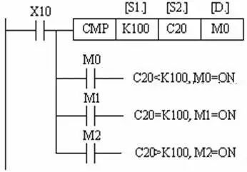
1. Compare instruction CMP
The CMP instruction has three operands: two source operands [S1.] and [S2.], and one destination operand [D.], which compares [S1.] and [S2.] and the result is sent to [ D.]. Use the CMP instruction as shown in the figure.
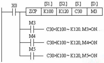
2, interval comparison instruction ZCP
The ZCP instruction compares an operand [S.] with the interval formed by two operands [S1.] and [S2.], and [S1.] must not be greater than [S2.] and the result is sent to [D.] . ZCP instruction instructions as shown.
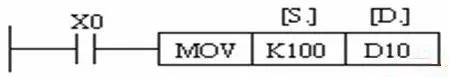
3, transfer instruction MOV
The MOV instruction transfers the source operand data to the target element, ie, [S.] → [D.]. The instructions for using the MOV instruction are shown in the figure. When X0 is ON, the data K100 in the source operand [S.] is transferred to the target element D10. When X0 is OFF, the instruction is not executed and the data remains unchanged.
4, shift transfer instructions SMOV
First, the binary source data (D1) is converted into a BCD code, and then the BCD code is shifted and transmitted to achieve data distribution and combination. The 2 bits (m2=2) from the 4th bit (m1=4) from the right of the source data BCD code are shifted to the 3rd bit (n=3) and 2nd bit of the destination D2/, and the 4th sum of D2/ The first two BCDs remain unchanged. Then, the BCD code in target D2/ is automatically converted to a binary number, which is the content of D2. An error occurred when the BCD code value exceeded 9999.
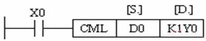
5, reverse the transfer instruction CML
The instructions for using CML instructions are shown in the figure. The data in the source operand (automatically converted to a binary number) is inverted bit by bit and transmitted.
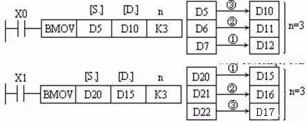
6, block transfer instructions BMOV
The BMOV instruction transfers a block of n numbers starting from the element specified by the source operand to the specified destination. If the element number exceeds the allowable element number range, the data is transferred only to the allowable range. The instructions for using the BMOV instruction are shown in the figure.
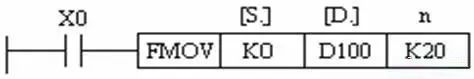
7. Multicast instructions FMOV
The FMOV instruction transfers the data in the source element to the n target elements from the beginning of the specified destination. The data in the n elements is exactly the same. Instructions for use of the FMOV instruction are shown in the figure.
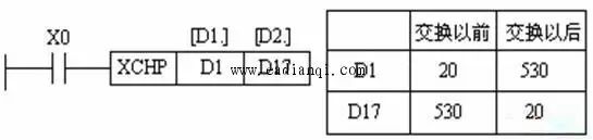
8, data exchange instructions XCH
The XCH instruction exchanges the contents of the two target elements D1 and D2. Use instructions as shown.
9, BCD conversion, BIN conversion instructions
BCD is to convert the binary number in the source element to the BCD code to the target element. For 16-bit or 32-bit binary operands, an error occurs if the conversion result exceeds the range of 0-9999 or 0-99999999.
The BCD instruction is often used to convert a binary number in a PLC into a BCD code output to drive an LED display.
BIN is to convert the BCD code in the source element to a binary number and send it to the target element. The constant K cannot be used as the operating element of this instruction. An error occurs if the source operand is not a BCD code.
The BIN instruction is often used to input the set value of the BCD digital switch to the PLC.
Case: Cargo Control 1. Control Requirements
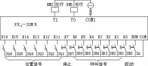
A workshop has 6 work stations. Feeders shuttle between the work stations. Each work station has an on-position switch (SQ) and a breather button (SB).
Specific control requirements are as follows:
(1) The feeder car should be able to stay at any of the six worktables in place.
(2) Assuming that the feeder car is currently suspended at worktable M (SQ m is ON), then work station number n calls (SQ n is ON), if:
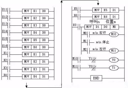
(a) m>n, feed the car to the left, until SQ n moves, stop in place. That is, when the number of the stop position of the feeder car SQ is greater than the number of the call button SB, the feeder car moves to the left to the stop position and then stops.
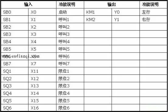
(b) m (c) m=n, the feeder does not move in situ. That is, the feeder car does not move when the number of the stop position SQ of the feeder car is the same as the number of the call button SB. Second, the realization of PLC hardware 1, the I / O allocation table 2. External wiring of I/O Third, the realization of PLC software In the figure, the current position of the feeder is sent to the data register D0, the calling station number is sent to the data register D1, and then the running direction and the target position of the feeder are determined by comparing the data in D0 and D1.
If you are tired of the original back of your phone, you should try our 3D Relief Back Sticker. The Back Skin Protective Film on the back can not only bring you a visual change, but also protect the back cover of the phone itself from scratches and collisions. Real 3D touch, personalized and stylish pattern design. Bring you a perfect experience.
In daily use, it can protect the equipment from scratches, dust, impact and other damage.
Long-lasting anti-scratch effect, significantly reducing dust, oil stains and fingerprint stains.
Easy to install, easy to stick to the back of the phone, and will not damage the original appearance of the phone.
With the Protective Film Cutting Machine, you can install the Back Film on different types of mobile phone back shells, including mobile phones, tablet computers and other electronic products. Customization can be completed in 30 seconds with just one click.
If you want to know more about 3D Relief Back Sticker, please click product details to view the parameters, models, pictures, prices and other information about 3D Relief Back Sticker.
Whether you are a group or an individual, we will try our best to provide you with accurate and comprehensive information about 3D Relief Back Sticker!
3D Phone Sticker, Carbon Fiber Back Sticker, 3D Relief Back Sticker, 3D Printing Back Sticker, Phone Skin,Mobile Phone Back Sticker
Shenzhen Jianjiantong Technology Co., Ltd. , https://www.jjtphonesticker.com