The ultrasonic emission circuit diagram is shown below. The magnitude of the applied voltage of the ultrasonic transducer is an important factor in determining the distance of the detection. The applied voltage can affect the electric field strength of the piezoelectric ceramic material inside the transducer, which in turn affects the diaphragm shape variable and the piezoelectric conversion efficiency. One method currently used is to use the 7404 series inverter as the voltage driving chip of the ultrasonic transmitting transducer. Although this scheme is simple in design and low in price, it generates a lower peak-to-peak voltage and the highest Only about 7v, the detection distance is greatly shortened. In response to this situation, this paper decided to use MAX232 instead of the inverter to increase the emission driving voltage of the ultrasonic transducer by push-pull method and improve the piezoelectric conversion efficiency. Through experiments, the MAX232 can convert a TTL level of about 5v to a 232 level of about 9.2v, with a peak-to-peak value of 18.5v, a detection range of up to 5m, and a duty cycle of approximately 50%, overcoming the detection distance. The shortcomings, and other performance indicators fully meet the design requirements. The ultrasonic wave sent by this scheme takes 10 cycles as a sequence, and the two sequences are separated by 32768us, that is, the time when the T1 timer overflows. When T1 overflows, the system displays an error and re-transmits the ultrasonic wave to the next measurement. The system transmission circuit is shown in Figure 2.
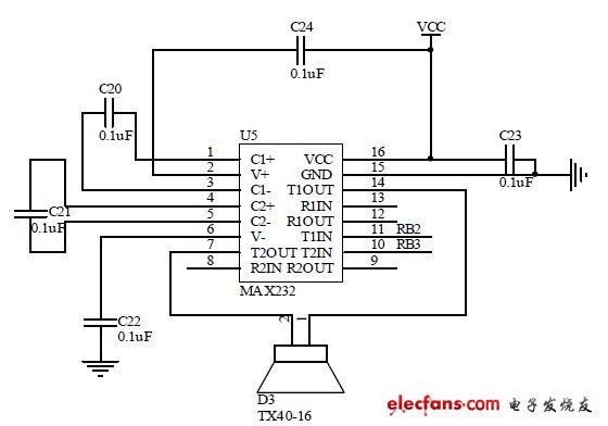
Diagram system transmission circuit diagram
BIOTEPT 1/4 HP 3/4 hp. 1hp. 2hp General Purpose Motor, 3 phase, 1200 RPM, 208-230/460 V, 56C Frame, TEFC TENV ODP All acceptable


56 Frame Motor,56C Frame Single Phase Motor,56C Frame Motor ,56C Motor
Ningbo Biote Mechanical Electrical Co.,Ltd , https://www.biotept.com