This article takes a rich case study of switching power supplies to introduce single-ended forward switching power supplies, self-oscillating switching power supplies, push-pull switching power supplies, step-down switching power supplies, step-up switching power supplies, and inverting switching power supplies. With the global attention to energy issues, the problem of energy consumption of electronic products will become increasingly prominent. How to reduce standby power consumption and improve power supply efficiency has become an urgent problem to be solved. Although the traditional linear regulated power supply has a simple circuit structure and reliable operation, it has the disadvantages of low efficiency (only 40%-50%), large volume, large consumption of copper and iron, high operating temperature, and small adjustment range. In order to improve efficiency, people have developed a switch-mode regulated power supply, which has an efficiency of more than 85% and a wide voltage range. In addition, it has a high voltage regulation accuracy and does not use power transformers. Ideal regulated power supply. Because of this, switch-mode regulated power supplies have been widely used in various electronic devices. This article describes the working principles of various types of switching power supplies.
First, the basic working principle of switching power supply
There are two types of switch-mode regulated power supply control methods: adjustable-width modulation and frequency-modulation. In actual applications, the wide-ranging type is used more often. Most of the switching power supply ICs currently developed and used are also Pulse width modulation type. Therefore, the following describes the wide-range switching power supply. The basic principle of the widened switching power supply can be seen in the figure below.
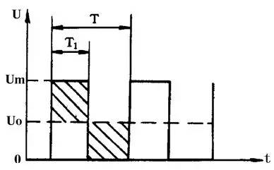
For a unipolar rectangular pulse, the DC average voltage Uo depends on the width of the rectangular pulse. The wider the pulse, the higher the DC average voltage. DC average voltage U. Can be calculated by formula
That is Uo=Um×T1/T
Where Um is the maximum voltage value of the rectangular pulse; T is the rectangular pulse period; T1 is the rectangular pulse width.
It can be seen from the above equation that when Um and T are constant, the DC average voltage Uo will be proportional to the pulse width T1. In this way, as long as we try to make the pulse width narrow with the increase of the output voltage of the regulated power supply, the purpose of stabilizing the voltage can be achieved.
Second, the principle of switching power supply circuit diagram
1, the basic circuit
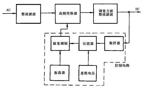
Figure 2 shows the basic circuit block diagram of the switching power supply
The basic block diagram of the switching regulator power supply is shown in Figure 2. After the AC voltage is rectified and filtered by the rectifying circuit and the filter circuit, it becomes a DC voltage with a certain pulsating component. The voltage enters the high frequency converter and is converted into a square wave of a desired voltage value, and finally the square wave voltage is rectified. The filter becomes the required DC voltage. The control circuit is a pulse width modulator, which is mainly composed of a sampler, a comparator, an oscillator, a pulse width modulation, and a reference voltage. This part of the circuit has now been integrated into a variety of integrated circuits for switching power supplies. The control circuit is used to adjust the switching time ratio of the high-frequency switching element so as to achieve the purpose of stabilizing the output voltage.
2. A typical circuit of a single-ended flyback switching power supply single-ended flyback switching power supply is shown in Figure 3. The so-called single-ended in the circuit means that the core of the high frequency converter only works on the side of the hysteresis loop. The so-called back-fence means that when the switch VT1 is turned on, the induced voltage of the primary winding of the high-frequency transformer T is positive and negative, and the rectifier diode VD1 is in an off state, and energy is stored in the primary winding. When the switch tube VT1 is turned off, the energy stored in the primary winding of the transformer T is output through the secondary winding and the VD1 rectifying and capacitor C filtering to the load.
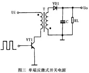
The single-ended flyback switching power supply is a kind of power circuit with the lowest cost, and the output power is 20-100W. It can output different voltages at the same time and has better voltage regulation rate. The only drawback is that the output ripple voltage is large and the external characteristics are poor, suitable for relatively fixed loads. The maximum reverse voltage applied to the switch VT1 of the single-ended flyback switching power supply is twice the operating voltage of the circuit and the operating frequency is between 20-200 kHz.
3. A typical circuit of a single-ended forward switching power supply single-ended forward switching power supply is shown in FIG.
This circuit is similar in form to a single-ended flyback circuit, but its operation is different. When the switch VT1 is turned on, VD2 is also turned on. At this time, the grid transmits energy to the load, and the filter inductor L stores energy. When the switch VT1 is turned off, the inductor L continues to release energy to the load through the freewheeling diode VD3.

A clamp coil and a diode VD2 are also provided in the circuit, which can limit the maximum voltage of the switch tube VT1 between twice the power supply voltage. To meet the core reset condition, that is, the flux build-up and reset times should be equal, the duty cycle of the pulse in the circuit cannot be greater than 50%. Because this kind of circuit transmits energy to the load through the transformer when the switch tube VT1 turns on, so the range of output power is great, can output the power of 50-200W. The transformer used in the circuit has a complex structure and a large volume. For this reason, the practical application of such a circuit is less.
4. Self-oscillating switching regulator power supply Self-oscillating switching regulator power supply of the typical circuit shown in Figure 5.
This is a kind of switching power supply that uses an intermittent oscillation circuit and is one of the basic power supplies that are widely used at present.
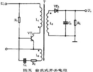
When the power is turned on, R1 provides a starting current to the switch VT1 so that the VT1 starts to conduct. The collector current Ic linearly increases in L1, and a positive feedback voltage is induced in the L2 to make the VT1 base positive and the emitter negative. , VT1 quickly saturated. At the same time, the inductive voltage charges C1. As the charging voltage of C1 increases, the base potential of VT1 gradually becomes lower, causing VT1 to exit the saturation region, and Ic starts to decrease. Inductance is induced in L2 to make the base of VT1 negative, and the emitter is The positive voltage causes the VT1 to rapidly cut off. At this time, the diode VD1 is turned on, and the energy stored in the primary winding of the high-frequency transformer T is released to the load. When VT1 is cut off, there is no induced voltage in L2, and the DC power input voltage is reversely charged by R1 to C1, gradually increasing the VT1 base potential, making it re-conducted, turning it over again to reach saturation, and the circuit is repeatedly oscillating. . Here, like a single-ended flyback switching power supply, the voltage required by the secondary winding of the transformer T is output to the load. The switch tube in the self-excited switching power supply serves as a dual switch and oscillation and also eliminates the need for a control circuit. In the circuit, since the load is located in the secondary of the transformer and operates in the flyback state, the input and output are separated from each other. This circuit is not only suitable for high-power power supplies, but also for low-power power supplies.
5. A typical circuit of a push-pull switching power supply with a push-pull switching power supply is shown in Figure 6.
It belongs to the double-ended conversion circuit. The core of the high-frequency transformer works on both sides of the hysteresis loop. The circuit uses two switch tubes VT1 and VT2. The two switch tubes alternately turn on and off under the control of the external excitation square wave signal. The square wave voltage is obtained in the secondary group of the transformer T, and the rectified filter becomes the required DC. Voltage.
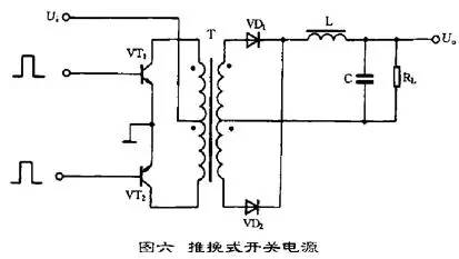
The advantage of this circuit is that the two switch tubes can be easily driven. The main disadvantage is that the withstand voltage of the switch tube is twice the peak voltage of the circuit. The output power of the circuit is relatively large, generally in the range of 100-500W.
6. A typical circuit of a buck switching power supply buck switching power supply is shown in FIG.
When the switch VT1 is turned on, the diode VD1 is turned off, and the rectified voltage of the input is charged to C by VT1 and L. This current increases the energy stored in the inductor L. When the switch VT1 is turned off, the inductor L induces a left-right negative voltage, and the energy stored in the inductor L is released by the load RL and the free-wheeling diode VD1 to maintain the output DC voltage unchanged. The circuit output DC voltage is determined by the width of the pulse applied to the VT1 base.
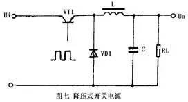
This kind of circuit uses few components. It is the same as the other two circuits described below. It only needs to use inductors, capacitors, and diodes.
7. Step-up switching power supply
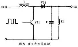
Step-up switching power regulator circuit shown in Figure 8. When the switch VT1 is turned on, the inductor L stores energy. When the switch VT1 is turned off, the inductor L induces a left-right negative positive voltage. The voltage is superimposed on the input voltage and is supplied to the load via the diode VD1 so that the output voltage is greater than the input voltage to form a boost-type switching power supply.
8. The typical circuit of the inverting switching power supply inverting switching power supply is shown in Figure 9. This circuit is also called a buck-boost switching power supply. No matter whether the pulsating DC voltage before the VT1 switch is higher or lower than the stable voltage at the output, the circuit can work normally.
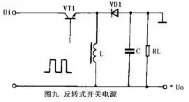
When the switch VT1 is turned on, the inductor L stores energy, the diode VD1 is turned off, and the load RL is powered by the charged charge of the capacitor C last time. When the switch VT1 is turned off, the current in the inductor L continues to flow, and a positive and negative voltage is induced. The diode VD1 supplies power to the load and charges the capacitor C. The basic working principle and various circuit types of pulse-width modulation type switching power supply are introduced above. In practical applications, there will be various kinds of actual control circuits, but no matter what, they are all developed on these foundations. of.
PS5 Vertical Stand Cooling Fan
Our vertical stand some are multifunctional ,some with Headset holder.
- [All in One]Designed specifically for the PlayStation 5 console (Disc or Digital versions), the DualSense controller, and PS5 game cases, this black cooling stand perfectly matches the aesthetic design of the PS5.
- [Efficient Cooling System]The dual-fan cooling system dissipates heat from your PS5 console quickly and efficiently. Variable speed fans power up or down based on the cooling needs of your system, for low noise output while maintaining maximum cooling efficiency.
- [Dual Controller Charger]Charge up to two DualSense wireless controllers at the same time using fast charge technology without having to connect them to your PS5 console. The click-in USB Type-C controller charger adapter is easy to use and protects your controller shell from scratches.
- [Multifunctional Stand]Includes extra USB port that can be used to charge or connect to other external devices like tablets, phones, and cameras for data transfer and charging.
-
[Headset and Remote Holder]Detachable headset stand with 2 cable hooks, firm and stable for your PULSE 3D wireless headset; moreover, always put your media remote down on the same, designated holder when not in use saves you much precious time looking for it next time


Ps5 Vertical Stand Cooling Fan,Ps5 Console Cooling Fan Stand,Ps5 Vertical Stand,Vertical Stand
Shenzhen GEME electronics Co,.Ltd , https://www.gemesz.com