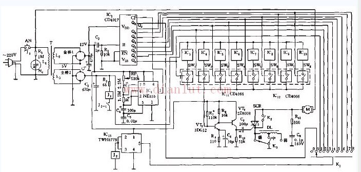
The simulated natural wind control circuit is shown in the figure. The controller is composed of a voltage drop rectifier circuit, a clock signal source, a counting distributor, a random signal source, an analog switch, a timing selection switch, and a thyristor control circuit. The buck rectifier circuit provides a DC voltage to the entire controller.
When the power is turned on, the multi-vibrator consisting of IC (555) and R4, R5, R6, C4, etc. starts to oscillate, and its oscillation period is T=0.639 (R4R52R6)C4, and the period corresponding to the illustrated parameter is about 5 second. Its output signal is applied to the CP terminal 14 of IC2 as a clock signal.
Led Poster,Digital Led Poster,Led Light Poster,Led Poster Display
ShenZhen Megagem Tech Co.,Ltd , https://www.megleddisplay.com