1 traditional street lighting
At present, the types of light sources used for street lighting are mainly metal halide lamps, incandescent lamps and high pressure sodium lamps. Among them, high pressure sodium lamps are widely used due to their high luminous efficiency, long life, and strong penetrability. Its basic optical structure consists of a light source, a reflector and a transparent lampshade. Since the light radiation of the light source occupies almost the entire space, it is necessary to adopt the light distribution design of the optical system of the street lamp to achieve the luminosity parameter of the national standard street lamp. Generally, the reflector of a high-pressure mercury lamp type street lamp uses a parabolic groove for light distribution. It can adjust the light to illuminate in the desired area: and using LED as the light source of the new street lighting, it is necessary to seek a new light distribution model to illuminate the LED light source to achieve the luminosity index of the street lighting.
2 LED street light optical design ideas
2.1 LED street light optical system
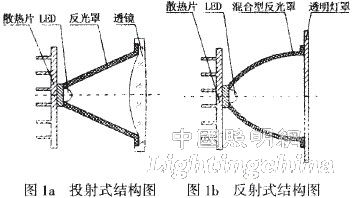
There are two types of optical structures for LED street lamps: projection and 1 reflection. The projection streetlight optical structure usually consists of a rotating parabolic plow reflector and a lens, but a single such structure does not meet the lighting requirements of street lighting, so a lens must be used for re-dispensing, as shown in Figure 1a. This method requires a high degree of cooperation between the reflector and the lens, which makes it difficult to design, install and maintain. The reflective optical structure, as shown in Figure lb, is used by more and more optical designers because it only needs to be used for the light distribution design of the reflector. This paper also uses a reflective optical structure and a hybrid structure design of the reflector.
2.2 Illumination optics computer aided design
Illumination optics training belongs to non-imaging optical juices. It mainly studies optical systems from the perspective of energy transfer law. Basically, non-sequential ray tracing is used. The commonly used method for calculating illuminance is Monte Carlo method. This article uses Tracepm optical simulation software for simulation. The basic steps of the design are as follows:
(1) determining the number of LED light sources, establishing a model of the light source and setting its parameters;
(2) establishing a three-dimensional model of the hybrid reflector structure;
(3) Determine the arrangement of the LED light sources and simulate using optical software;
(4) Analyze the simulation results and compare the difference between the simulation results and the road lighting distribution requirements;
(5) According to the difference in the simulation results or the part that does not meet the requirements, the parameters of the shed should be repeatedly corrected until the juice requirement is met.
2.3 Hybrid structural design
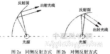
At present, reflective optical structures have been applied in more and more fields, and the difficulty lies in the fact that the reflector structure is not designed, that is, how to design a reflective surface type that meets the required optical illumination light distribution requirements. In order to direct the reflected light to a specified illumination area, there are two possible ways, that is, the light emitted by the light source is reflected toward the side and reflected to the opposite side, as shown in Figures 2a and 2b, respectively.
In view of the requirements of the illuminating characteristics and illumination range of the LED light source used, the reflective surface patterns in the X direction and the Y direction are designed to reflect the on-site road lighting. The light source is placed at the front focus F1 of the ellipsoid, as shown in Figure 3, which is an ellipsoidal reflection surface model.
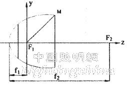
Figure 3 ellipsoid reflection surface model
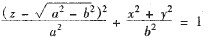
The expression equation of the ellipsoidal reflection surface is:
 (Formula 1)
Where a and b are the semi-major axis and the semi-minor axis of the ellipsoid, respectively.
And f1, f2 in Fig. 3 respectively represent the distance from the ellipsoid vertice to the two focal points F1 and F2, and the expressions are as follows:
 (Formula 2)
By adjusting the dimensions of the long and short axes a and b of the ellipsoid, the length of the semi-focal length of the ellipsoidal reflecting surface can be changed, so that the angle of the outgoing light can be changed to ensure that the outgoing light can be illuminated in the desired illumination area.