Aiming at the problem that there is no remote anti-theft function in the current automotive PKE system, a design scheme of automotive PKE system with remote anti-theft function based on STC single-chip microcomputer is proposed. The high-frequency transmission and low-frequency wake-up receiving circuit of the key module, the high-frequency receiving and low-frequency transmitting circuit of the vehicle module, and the communication connection between the vehicle module and the GSM module are designed. The rolling code encryption and decryption process and the communication protocol between the key module and the vehicle module are analyzed. This design solution completes the PKE anti-theft function and can meet the anti-theft and communication requirements in practical applications.
Keywords remote anti-theft; rolling code; GSM module; low frequency wake-up
Since the 1990s, electronic information technology has been widely used in car anti-theft systems, which has promoted the intelligence and diversification of car anti-theft technology. Passive Keyless Entry (PKE) is rapidly becoming the mainstream of automotive access control systems and a popular choice for new cars.
The remote anti-theft car PKE system design proposed in the paper combines network technology, high and low frequency two-way communication and other related technologies. The owner of the car with the key only needs to be close to the door and the door will open automatically. In addition, based on the traditional PKE function, the G1obal System for Mobile Communications (GSM) module is applied to make up for the shortcomings of the existing car PKE system that cannot realize the remote anti-theft function. In foreign countries, the PKE system has become the mainstream configuration of high-end models, and is also used in medium and low-end models. At present, the system is still monopolized by foreign companies, but domestic research in this area has just started. With the rapid expansion of the domestic automobile market, research and design of automotive PKE system with network anti-theft function has great practical value.
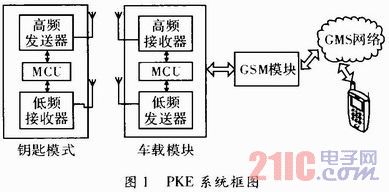
1 PKE system framework The whole system consists of two parts: the key module and the vehicle module. The on-board module MCU (Micro Control Unit) automatically transmits a low-frequency signal of 125 kHz by programming at a certain interval. When the low-frequency wake-up chip of the key module detects the effective low-frequency signal, the key module MCU is awakened to control the high-frequency transmitting module to encrypt the signal. The 520 MHz high frequency information is sent out; after receiving the 315 MHz high frequency information, the vehicle module transmits it to the vehicle MCU, which is responsible for receiving, decoding, discriminating and correspondingly processing the data to complete the corresponding action. When the owner leaves the car, as long as the vibration sensor of the vehicle body detects the vibration, an alarm is issued, and the vehicle MCU controls the GSM module to send a text message to the owner's mobile phone. The structural block diagram of the system is shown in Figure 1.
This article refers to the address: http://
2 Key module hardware design The key module MCU selects STC12C5201AD low-power single-chip microcomputer, and cooperates with low-frequency wake-up receiving circuit and high-frequency transmitting circuit to form a key module. The MCU is generally in an ultra-low power receive mode and operates in an interrupt mode. The key module MCU is only woken up when a valid low frequency signal input or key press is detected to reduce system power consumption.
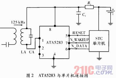
2.1 Low-Frequency Wake-up Module The low-frequency receiver chip uses the ATA5283 chip, which has a wake-up function of 125 kHz ultra-low power receiver. The input terminal amplifies and processes the signal packet received from the antenna and converts it into data output to the single chip microcomputer. When a 125 kHz signal is received, the ATA5283 activates its N_WAKEUP and N_DATA (data output pins). When idle, the ATA5283 and the MCU are in standby state. When the resonant circuit receives the 125 kHz valid signal, N_WAKEUP wakes up the MCU and starts to work. Then the MCU gives the ATA5283 RESET pin a high level to reset it and enter the standby mode. The ATA5283 is connected to the microcontroller as shown in Figure 2.
2.2 High-frequency transmitting module The high-frequency transmitting module consists of a surface acoustic wave oscillating circuit and a modulation circuit of 315 MHz in the south. The oscillation or oscillation of the oscillating circuit is controlled by the PWM signal output by the single-chip microcomputer. Since the STC microcontroller has no signal encryption function, the Keeloq encoding encryption chip is added to the key module to realize signal encryption.
3 Car module hardware design The car module MCU uses STC12C15204AD MCU, which has 4 kB Flash user application space, which can be used to decode encrypted signals. The single chip microcomputer and the high frequency receiving module, the low frequency transmitting circuit, the vibration alarm module and the CSM communication module constitute the in-vehicle module of the system.
3.1 Low-frequency transmitting circuit The low-frequency transmitting module uses the special chip TC4422, its output impedance is only 1.6 Ω, and the driving current can reach 9 A. The MCU sends the signal to the IN pin of the TC4422, which then drives the antenna coil to send a low frequency signal of 125 kHz.
3.2 High-frequency receiving circuit The high-frequency receiving adopts the wireless receiving chip RX3400, which has better anti-interference characteristics and is suitable for single-chip data transmission. After receiving the Amplitude Shift Keying (ASK) signal transmitted by the key module, the vehicle module transmits the signal to the RX3400 module for processing, and then obtains the data signal, and then sends it to the vehicle module MCU after decoding, triggering the interrupt generation. , to make the microprocessor execute the corresponding processing program. Taking into account factors such as cost, the system uses software methods to decode.
3.3 Vibration alarm circuit Vibration detection is used to make an alarm in time when the vehicle body is detected to be in collision. The function module adopts the common automobile vibration sensor on the market. The output line of the sensor is connected with the IO port of the MCU of the vehicle module, and a 10-20 kΩ resistor is pulled up to keep the high level normally. When the vibration is generated, it is Pulled low, so the microcontroller controls the alarm circuit alarm.
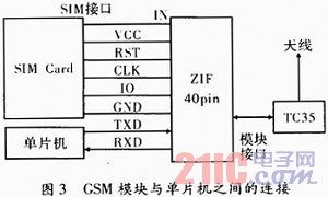
3.4 GSM communication module GSM module adopts Siemens TC35i module, can transmit voice and data signals, and connects SIM (Subseriber Identity Modu le) card reader and antenna through interface connector and antenna connector respectively, its data interface The AT command can transfer instructions and data in both directions, support text and pdu formats, and restart and recover faults through AT commands or shutdown signals. The circuit is simple to connect and uses asynchronous serial communication. The alarm short message is sent to the owner's mobile phone through the TC35i module. After receiving the alarm, the owner can send a short message to the TC35i module. The TC35i extracts the short message and decodes it to perform the corresponding operation to start the execution module. The connection between the GSM module and the microcontroller is shown in Figure 3.
4 system software design The software design part of the system mainly includes rolling code technology, system communication protocol and vehicle module process design.
4.1 Rolling code technology The rolling code (Keeloq) technology is a nonlinear encryption algorithm whose core components are: manufacturer code, serial number, and coded password. The manufacturer code is the original password determined by the manufacturer to identify different manufacturers; the serial number is used to distinguish different keys, each key has its own serial number; the coded password is used to generate the rolling code and is stored in the encryption chip. In-chip EEPROM. Due to the complexity of the Keeloq algorithm and the 16-bit sync code being updated each time it is transmitted, each transfer code is different from the last code. It can only be repeated after 216 transmissions, so it is difficult to be deciphered in a short time, ensuring security.
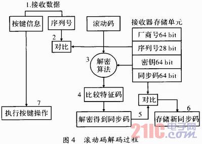
After receiving the high frequency encrypted signal, the onboard module demodulates and then decodes by software. The decoding steps are:
(1) After receiving the 66 bit encrypted data, the onboard module first checks whether the serial number in the fixed code is consistent with the serial number stored in the EEPROM.
(2) Run the decryption algorithm to get the identification code, synchronization counter value, function key, and overflow.
(3) The MCU compares the decoded identification code with the lower 10 bits of the serial number in the fixed code, and whether they are equal.
(4) Compare the decoded function key value with the function key value in the fixed code.
(5) It is judged whether the decoded synchronization count value and the old synchronization count value in the EEPROM are reasonably increased.
If there is an error in the above steps, the vehicle MCU does not perform the next action. The decoding process is shown in Figure 4.
4.2 Communication Protocol Low frequency communication between the low frequency transmitter of the vehicle module and the ATA5283 chip is used. The ATA5283 is in standby mode until a valid low frequency signal is detected. To prevent erroneous operation of circuits in noisy environments, the header detection circuit checks the input signal. The valid input signal is detected by the counter after 192 uninterrupted carrier cycles. After the effective carrier signal is found, the circuit turns on automatic gain control, and the complete header should have at least 704 carrier cycles. After that, the header ends and the data transmission process begins.
The high-frequency communication between the vehicle module and the key module uses the Pulse Width Modulation (PWM) coding method for half-duplex communication. One logical data is composed of three bits, and the value of the bit period Te is usually between 100 and 400 μs. Before receiving the PWM, the onboard module MCU prepares for receiving data through the guidance of the preamble data. After the synchronous guidance, when the microcontroller detects the first rising edge, it waits for 1/2Te time to sample immediately and detects whether it is high level 1. If it is 0, the data reception fails, and then delays a Te time immediately. Sampling is used as a data bit, and then delays a Te time to sample and judge. If it is high level 1, the data is failed to receive, and finally wait for the next rising edge. If the waiting time exceeds one Te, the data reception fails. Cycle through this until all the data has been received.
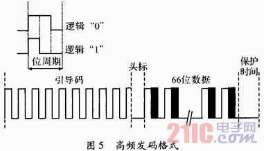
The high frequency symbol information consists of three parts: each time the code word is coded starting with the pilot code and the header, then the 66 bits of data, ie the rolling code and the fixed code, and finally the guard time for each transmission. The rolling code is 32 bit encrypted data; the fixed code is 34 bit. The high frequency data transmission format is shown in Figure 5.
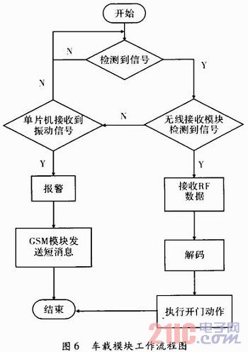
4.3 Vehicle Module Process The function of the vehicle module is to communicate with the high and low frequency of the key module, control the GSM module to send and receive short messages, control alarms, and read short messages in the SIM card. The MCU should correctly receive the data sent by the serial port, and can automatically analyze the data format sent by the TC35i to determine whether the sent command needs to be processed. In addition, if the system detects the vibration information of the body sensor, the system continuously sends a short message to the owner's mobile phone until the owner's mobile phone responds with a "stop" command.
5 Conclusion The system has the following characteristics: a master chip works in interrupt mode, which reduces the system power consumption; second, combined with rolling code encryption technology to achieve signal encryption, preventing signals from being intercepted and cracked, improving security; third, adding GSM communication module, The short-message control of various functions of the anti-theft system, solving the remote control problem of the anti-theft device of the car, and effectively improving the anti-theft performance of the car.
Interchangeable Power Adapter: Simplifying Your Power Needs
As a leading manufacturer of ac power adapter, we understand the importance of providing efficient and versatile power solutions for our customers. In today's fast-paced world, having an interchangeable plug power adapter is essential.
1. Travel-Friendly:
For frequent travelers, carrying multiple chargers for different countries can be inconvenient and space-consuming. Multi plug power adapter is the perfect solution for those on the go.With EU US UK AU 4 plug detachable, you can travel to USA Europe UK Australia and charge more convenient.
2. Safety and Efficiency:
Safety is a top priority when it comes to switching power supply. Our changeable power adapter is built with advanced safety features, including over-voltage protection, short-circuit protection, and over-current protection, to safeguard both the adapter and the connected devices. With safety and efficiency in mind, our interchangeable power adapters offer peace of mind to users.
In conclusion, interchangeable power adapters offer a convenient and versatile charging solution for users. Their ability to work in various countries, travel-friendly design,emphasis on safety and efficiency make them an ideal choice for individuals seeking a simplified charging experience. As a trusted switching power supply manufacturer, we are committed to providing high-quality interchangeable ac adapter that meet the evolving needs of our customers. Choose our ac to dc power adapter and enjoy the convenience they bring to your charging routine.
Interchangeable Power Adapter, multi plug power adapter, interchangeable plug power adapter, detachable power adapter
Guangdong Mingxin Power Technologies Co.,Ltd. , https://www.mxpowersupply.com