A resolver is a mechanical or analog sensor that can be used to determine the absolute position and speed of a motor. The resolver sensor can be used in harsh environments to help obtain accurate angular position and velocity data. These sensors are commonly used in the industrial, automotive and aerospace industries – especially in harsh environments where motors or sensors can be contaminated.
Common contaminants include: oil, dirt, food particles, and even extreme temperatures that may cause other rotational sensing techniques to fail. Specific end products have unique design challenges and requirements, some of which are common in most industrial applications. Two of the challenges are: 1) absolute accuracy of angular position and velocity data; 2) minimizing or eliminating electromagnetic interference (EMI).
Industrial application of resolver sensors
Some absolute rotation sensing technologies, such as optical encoders, have been selected for industrial applications multiple times. However, a resolver is an ideal choice when dealing with harsh environments or for low cost considerations. Servo motors are commonly used in the industrial field and are connected to resolvers and other types of position sensors. Applications that typically use servo motors and servo drives with resolvers to achieve angular velocity and position measurements include:
CNC (CNC) and injection molding machines, lifts, robotic arms, electric vehicles (electric bicycles, electric scooters, electric wheelchairs, etc.), rail transport, agricultural and construction equipment, buses and heavy trucks, golf carts and low-speed electric vehicles .
Main rotary transformer sensing system requirements
Accurate and timely resolver angle output
Before finding a way to use a resolver to mitigate the effects of electromagnetic interference on industrial systems, it is important to understand why accurate position control is essential. The resolver provides an analog output that is theoretically identical to infinite resolution. Analog to digital conversion techniques limit the resolution by dividing the output into blocks or steps. A limited segmentation of the persistence angle will result in a quantitative error. For example, you can use a 12-bit resolution converter to provide angular output. The rotation of the converter shaft is divided into 4096 steps (2^12 corresponds to a 12-bit resolution). Since once equal to 60 points, one revolution (360 degrees) is equal to 21600 centimeters (60x360). Then the interval between each step is 5.27 cents (21600/4096). The system is unlikely to provide better information than the 5.27 angle.
The two key points that determine the correct angular position are system accuracy and system settling time. The latter mainly refers to how long it takes for the angular output to show the exact position. Each component of the system needs to be evaluated to determine the limiting factors. In the system, the typical error accuracy is the sum of the resolver error and the resolver analog-to-digital conversion (RDC's) error. Most commonly, a resolver error occurs at 3-10 cents. In addition to the 5.27 angular point, there will be an analog to digital conversion error of the resolver, then we can get an accurate error range of 8.27 - 15.27 cents. Therefore, it is important to choose the right RDC. The following factors have an impact on system accuracy and settling time in typical resolver applications [1]:
Mechanical factor
Sensor structure (zero voltage, transformation ratio, etc.)
Sensor specifications as a function of temperature
Coil imbalance: sinusoidal and cosine coil output voltages may be unbalanced, resulting in errors
Rotary transformer sensor misalignment: The resolver may be incorrectly installed, resulting in system static error
The number of poles of the resolver sensor: since each additional pair of poles will detect 360 degrees more, the increased number of poles will reduce the angular error.
Electrical factor
Resolver analog-to-digital conversion structure
Time delay of the resolver signal input to the angular output, reacting to rapid angular change stabilization time
Imbalance of analog front end (AFE) components
The system has the ability to handle environmental factors (eg external magnetic field or common mode noise)
stable schedule
When the motor position or output signal of the resolver changes rapidly, the settling time is a fast performance indicator of the RDC control system [2]. Figure 1 shows an example of the settling time of an RDC feedback control system with step input changes (black lines). The blue signal shows the normal mode response to the circuit and the red signal shows the response during the acceleration mode (fast angular change). In order to track the angle of rotation under rapidly changing conditions, the acceleration mode helps the control loop to easily track a fast angle of rotation [4].
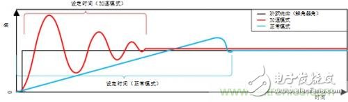
Figure 1: RDC step response settling time
EMC/EMI affects the rotary transformer system
Electromagnetic compatibility (EMC) refers to how an electronic system operates in an electromagnetic environment without causing problems (immunity). Similarly, the system transmit pulse must not interfere with any product in the range. Variable speed drives and control circuits are the primary sources of interference in industrial equipment applications. Fast switching of power components, such as insulated gate bipolar transistors (IGBTs) and microcontrollers, is a major source of high frequency emissions or interference. IGBT switching time can be as long as 100nS.
Electrical equipment should not be affected by high frequency phenomena, such as:
Electrostatic discharge (ESD)
2. Fast transients (also known as EFT)
3. Radiated electromagnetic field
4. Conducted radio frequency interference
5. Surge pulse
Restrictions are determined by industry standards such as the IEC 61800-3 standard that specifies electromagnetic compatibility requirements for variable speed drives that include AC/DC motors and control circuits. In such an environment, any design should follow established basic electrical design principles to mitigate the effects of noise [3].
1. Electronic PCB schematic and layout design:
a. separate power supply and analog grounding
b. Use an analog filter to eliminate common mode noise on the sensor signal
c. High frequency, low impedance filter for high frequency interference (eg ferrite beads)
d. Minimize the loopback area so that grounding provides the lowest possible impedance for the signal return path
2. Mechanical design:
a. Use armored cables and connectors (eg DB-9 armored connectors)
b. Wiring: Minimize cable length between drive and sensor components
c. Use armored twisted pair power supply and control cable to avoid interference
d. Use double armor to reduce radiation interference
Electromagnetic interference immunity requirements for variable speed drives
TI engineers tested the IEC61800-3 standard to obtain environmental specifications (Table 1). This design uses armored connectors and armored cables (length > 30m). The definition of the standard is shown in Table 2.
Environment 2
Connector test object benchmark level standard
Cabinet/box ESD IEC61000-4-2 4kV (8kV) CD or 8kV (15kV) AD 1) B
Radiation RF IEC61000-4-3 80-1000MHz, 10V/m, 80% AM (1kHz) A
Control signal and DC auxiliary power interface <60V EFT IEC61000-4-4 ±2kV (4kV)/5kHz, capacitive coupling B
Surge 1, 2/50us, 8/20us IEC61000-4-5 ±1kV (2kV): armored cable (2Ohm/500A); minimum length: 20m B
Conducted RF IEC61000-4-6 0.15-80 MHz, 10V/m, 80% AM (1kHz) A
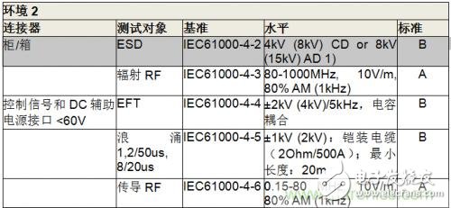
Table 1: EMC specifications for variable speed drives specified in IEC61800-3
Grade performance (pass) standard
A The module should continue to run as expected. There is no function or performance loss even when testing.
B Temporary performance degradation is acceptable. After testing, the module should continue to run as expected without manual intervention.
C During the test, the function is missing without damaging the hardware or software. After testing, the module should continue to run as expected after manual startup or shutdown.
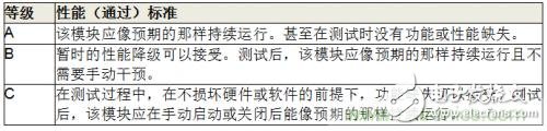
Table 2: IEC61800-3 Pass Performance Standards
Where does the EMI result come from?
Any high dl/dt or dV/dt may be an important potential source of electromagnetic interference (EMI). The EDGE rate of the electronic signal can produce harmonics and intermodulation distortion. For example, an EDGE rate of 10 ns on one side and an EDGE rate of 1 ns on the other side result in a square wave of 10 MHz. This shows how the increased harmonic content is accompanied by a square wave with a faster Edge Rate. Use Equation 1 as a general formula for calculating the harmonic frequency range at a specific Edge Rate:
(1)
According to this formula, the harmonic frequency corresponding to the 10nsEdge Rate is approximately 31.8MHz. Figure 3 shows that the last important harmonic frequency is 30 MHz. At the same time, the 1 ns Edge Rate corresponds to a harmonic frequency of 318 MHz (Figure 2). If the frequency range is extended beyond 300 MHz, the displayed harmonics are still noticeable, but they become rapidly smaller at the relevant frequencies.
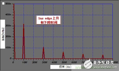
Figure 2: 10MHz square wave spectrum
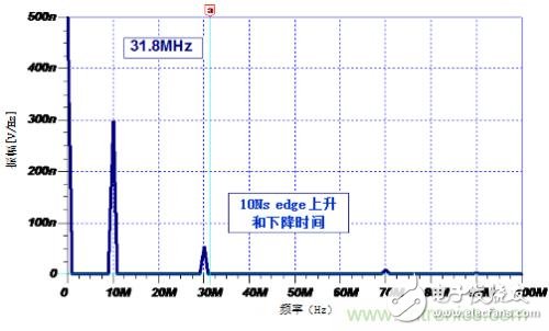
Figure 3: 31.8MHz square wave spectrum
These methods can help reduce the overall impact of noise on the accuracy of the resolver system:
1. Use differential signals to help reduce electrical noise in the cable
2. Armored cable noise is transmitted to the ground before it affects the sensor circuit and generates errors.
3. The analog front end (AFE) used in the RDC structure can filter out common mode noise
4. Strive for a near-perfect grounding with the lowest possible impedance
5. Minimize the loop that plays the role of the EMI antenna
Shielding and filtering
All conductive components, such as cables, ground, metal casings, etc., can transmit radiation. The transfer impedance of the cable must be less than 100 mΩ/m at frequencies up to 100 MHz. The highest shielding effect can be achieved with a metal or corrugated aluminum shield. The longer the cable path, the lower the required transfer impedance. Common mode inductors can be used in signal cables to reject common mode interference at a specific power. An ideal common mode inductor does not always have a differential mode signal. Faraday Cage technology is another commonly used method of controlling radiation interference.
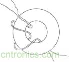
Figure 4: Example of turbulence suppressing common mode noise
in conclusion
The unique high precision and noise challenges in industrial motor position sensing applications can be addressed through comprehensive design considerations and careful electronic component selection. When designing a resolver, designers should consider system stability time specifications, EMI/EMC chip performance, and how these factors affect overall system accuracy.
Film capacitors are electrical capacitors with an insulating plastic film as the dielectric, sometimes combined with paper as carrier of the electrodes. These plastic films are sometimes metalized and are available in the market under the name metalized film capacitor,these capacitors are sometimes also called plastic capacitors.
Film Capacitor,X-Ray equipment Capacitor,Axial Polyester Capacitor,Polypropylene High Voltage Capacitor
XIAN STATE IMPORT & EXPORT CORP. , https://www.shvcomponents.com