Transistors have a large number of applications in our digital and analog circuits, and several transistors are used on our development boards. In the LED small light part of our board, there is the application of this transistor. The Q16 in the LED circuit of Figure 3-5 is a PNP type transistor.

Figure 3-5 LED circuit
The triode is a very common control and driving device. The commonly used triode is divided into two types according to the material: silicon tube and tantalum tube. The principle is the same, the voltage drop is slightly different, and the silicon tube is more common. Less, this course uses the parameters of the silicon tube to explain. There are two types of triodes, PNP and NPN. Let me know first, as shown in Figure 3-6.
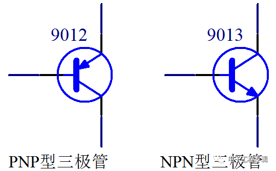
Figure 3-6 Schematic diagram of the triode
The triode has a total of 3 poles. As seen in Figure 3-6, the lateral left pin is called the base, with an arrow in the middle, one connected to the base, and the other connected to the emitter e (emitter). The remaining pin is the collector c (collector). This is something that must be remembered, rote memorization, and slowly use it later. Every time I remember it, I will go deep into my mind after many times.
The principle of the triode has three working states: cut-off, amplification, and saturation. The amplification state is mainly used in analog circuits, and the usage and calculation methods are also complicated, which we can't use for the time being. The digital circuit mainly uses the switching characteristics of the triode, and only uses the cut-off and saturation states, so we only explain the two usages. The type and usage of the triode I have summed up a sentence for everyone. Everyone should remember this sentence: the arrow is facing the inner PNP, the conduction voltage is going through the arrow, the voltage is on, and the current is controlled. Let's analyze the sentence one sentence at a time. You can see Figure 3-6. There are 2 types of triodes. The arrow is PNP inward. The natural arrow is NPN. In practical applications, you should choose which type to use according to the actual circuit requirements. It will be a few more times, it is very simple. The usage characteristics of the triode are the voltage between the b-pole (base) and the e-stage (emitter). For the PNP, the e-pole voltage is higher than the b-level above 0.7V. This transistor e-class and c The level can be smoothly turned on. That is, the console is between b and e, and the console is between e and c. Similarly, the turn-on voltage of the NPN transistor is bV is 0.7V higher than the e pole. In short, the start of the arrow is 0.7V higher than the end to turn on the e and c poles of the triode. This is the explanation of "the conduction voltage is going through the arrow and the voltage is on". Let's look at Figure 3-7.

Figure 3-7 Usage of the triode
Let us take an example of Figure 3-7. The base of the triode is connected to an IO port of the microcontroller through a 10K resistor. It is assumed to be P1.0, the emitter is directly connected to the 5V power supply, the collector is connected to an LED small lamp, and a 1K current limiting resistor is connected in series. Finally, it is connected to the negative power supply GND. If P1.0 is given a high level by our program, then both base b and emitter e are 5V, which means that e to b does not produce a voltage drop of 0.7V. At this time, the emitter and set The electrode will not turn on, then the circuit is turned off at the triode, and no current is passed, and the LED2 small lamp will not light. If the program gives P1.0 a low level 0, then the e pole is still 5V, so a voltage difference is generated between e and b, and the triodes e and b are also turned on, and there is probably a triode between e and b. A voltage drop of 0.7V, and the voltage of (5-0.7)V will be on resistor R47.
At this time, between e and c will also be turned on, then the LED small lamp itself has a voltage drop of 2V, and the transistor itself has a voltage drop of 0.2V between e and c, which we ignore. Then there will be a voltage drop of about 3V on R41, which can be calculated. The current of this branch is about 3mA, which can successfully illuminate the LED. The last concept, current control. As mentioned before, the triode has three states of cut-off, amplification, and saturation. It is not necessary to say the cut-off, as long as the conduction between e and b is not. We want to make this triode saturated, which is what we call the switching characteristics, must meet a condition. The triode has a magnification of β. To be saturated, the b-pole current must be greater than the current between e and c divided by β. This β is probably considered to be 100 for a commonly used triode.
Then the resistance of the upper R47 must be calculated. Just now we have calculated that the current between e and c is 3mA, then the minimum b current is 3mA divided by 100 equals 30uA, about 4.3V will fall on the base resistance, then the maximum base resistance is 4.3. V/30uA = 143K. The resistance value can be smaller than this value, of course, it can not be too small. If it is too small, the current of the IO port of the MCU will be too large to burn out the triode or the MCU. The maximum theoretical input value of the IO port of the STC89C52 is 25mA. I recommend not to exceed 6mA. We use the voltage and current to calculate the minimum resistance value. Figure 3-7 takes the empirical value.
Immersion Cooling is a technique used to cool components of IT equipment that consists of submerging the computer components in a thermally conductive and dielectric liquid. Through this practice, the servers are cooled and heat is transferred from the source to the liquid.
When we talk about Immersion Cooling, we also need to discuss the different types of Immersion Cooling, as well as the applications of Immersion cooling. The practice of Immersion Cooling has a multitude of benefits particularly as it allows datacenters to be managed in a greener and more sustainable manner. Environmental concerns has been a huge catalyst for the adoption of the technology in recent years.
deionized water
mineral oil
fluorocarbon-based fluids
synthetic
Immersion Cooling systems used to have a higher fluid cost than water cooling, but this is already changing.
A wide variety of liquids exist for this purpose, the most suitable being transformer oils and other electrical cooling oils. Non-purpose oils, including cooking, motor and silicone oils, have been successfully used for cooling personal computers
water cooling,oil cooling,immersion cooling box,liquid immersion cooling,apw12 power supply
Shenzhen YLHM Technology Co., Ltd. , https://www.asicminer-ylhm.com