Speech recognition is a technique in which a machine converts a human voice signal into a corresponding text or command through a process of recognition and understanding. The fundamental purpose is to develop a machine with auditory function. This design studies the isolated word speech recognition system and its implementation on the STM32 embedded platform. The identification process is: pre-filtering, ADC, framing, endpoint detection, pre-emphasis, windowing, feature extraction, feature matching. Endpoint Detection (VAD) combines a short-term amplitude with a short-term zero-crossing rate. After the effective speech is detected, the Mel frequency cepstral coefficient (MFCC) of each frame of speech is calculated according to the auditory perception characteristics of the human ear. Then use the dynamic time warping (DTW) algorithm to match the feature template, and finally output the recognition result. Firstly, the above algorithm is simulated by Matlab. After many experiments, the optimal values ​​of the coefficients required in the algorithm are obtained. Then the algorithm is transplanted to the STM32 embedded platform. During the migration process, the algorithm is optimized according to the actual situation that the embedded platform has relatively small storage space and relatively weak computing power. Finally, an STM32-based isolated speech recognition system was designed and produced.
Technically speaking, speech recognition belongs to the category of multidimensional pattern recognition and intelligent interfaces. It is a comprehensive technology integrating acoustics, phonetics, computer, information processing and artificial intelligence. It can be widely used in information processing, communication and electronic systems, automatic control and other fields.
International research on speech recognition began in the 1950s. Due to the inherent difficulty of speech recognition itself, research tasks under various conditions have been proposed, and this has led to different research fields. These areas include: for speakers, can be divided into specific speaker speech recognition and non-specific speaker speech recognition; for vocabulary, can be divided into small vocabulary, medium vocabulary and large vocabulary recognition, by speaking, can be Divided into isolated word recognition and continuous speech. The simplest areas of research are the recognition of specific speakers, small vocabulary, and isolated words. The most difficult areas of research are non-specific people, large vocabulary, and continuous speech recognition.
Before entering the new century, speech recognition technology was mostly used only in specific industries or places or just staying in the laboratory, in exploration and experimentation. The rise of the consumer electronics industry and the outbreak of mobile Internet technology in the last decade. More and more automation and self-energy products are coming into people's daily lives. Speech recognition technology has also entered the public's sight and began to be understood and used by more people. For example, voice access, voice switching on smart TV, voice dialing on smart phones, voice control, and so on. Speech recognition technology is taking the past experimental exploration into the practical stage. We have reason to believe that more and more products will use speech recognition technology, and its combination with artificial intelligence technology will be an important development direction. Speech recognition technology will eventually change the way people interact with machines, making them more natural, convenient, and easy.
The isolated speech recognition of this design is relatively basic in speech recognition technology, and the algorithm implementation is also simple, which is suitable for implementing some simple speech control functions in the embedded platform. In the past, similar systems were mostly based on ARM9, ARM11, DSP, SOC, etc. These platform systems are large in scale, difficult to develop and maintain, and relatively expensive. STM32 is a high-performance microcontroller based on the ARM Cortex-M3 core from STMicroelectronics. After the launch, due to its excellent performance and low price, it was quickly applied to many products. After testing, STM32F103VET6 MCU has the computing and storage capabilities needed to satisfy the isolated speech recognition of this system. Therefore, in this system, STM32F103VET6 is used as the main controller to collect and recognize the voice signal. The design goal of isolated speech recognition is completed with low cost and efficient algorithm. The main contents of this system are as follows:
Speech signal acquisition and front-end amplification, anti-aliasing filtering, analog-to-digital conversion.
Voice signal preprocessing, including pre-emphasis, framing, windowing.
Speech signal endpoint detection, detecting the start and end points of valid speech in the input signal
Speech signal feature extraction. A Mel Frequency Cepstral Coefficient (MFCC) coefficient of each frame of speech signal in the effective speech is extracted.
Template training, collecting multiple voice samples for each voice instruction, and acquiring feature templates of each voice instruction according to the voice samples.
Feature matching uses a dynamic time warping (DWT) algorithm to calculate the matching distance between the input speech signal and each template. Identify the input voice signal.
System hardware circuit design, man-machine interface design.
Chapter 1 Scheme Argument and Selection 1.1 System Design Task Requirements The system uses an MCU to design an isolated speech recognition system that can recognize 14 Chinese speeches from 0 to 9, “upâ€, “downâ€, “left†and “rightâ€. instruction. The system interacts with the user via a touch LCD.
The main requirements of this design are as follows:
1. Acquire external sound signals, convert them to digital signals and store them.
2. Find the start and end points of the valid speech signal in the acquired sound signal.
3. The detected valid speech is analyzed to obtain a speech signal characteristic.
4. A feature template is created for each voice instruction to be recognized.
5. Comparing input speech signal features and feature templates to identify input speech signals
6. Display system operation interface and be able to accept user control.
1.2 Hardware Selection 1.2.1 Hardware Solution General Introduction The system hardware consists of four parts: audio amplification module, MCU, touch screen and power supply. The audio amplification module performs acquisition and amplification of external sound signals. Convert the sound signal into an electrical signal and amplify it to 0~3V. The MCU's ADC reference voltage is 3.3V for its supply voltage. The output signal of the audio amplifier module does not exceed the voltage range of the MCU ADC and can achieve maximum quantization accuracy. The MCU performs AD conversion on the sound signal input by the audio amplification module. The signal characteristics are then extracted and identified. In addition, the MCU also controls the display of the touch screen and reads the touch screen click position. The touch screen is responsible for displaying the operation interface and receiving user operations. The power supply is battery powered.
The system hardware structure is shown in Figure 1.1.
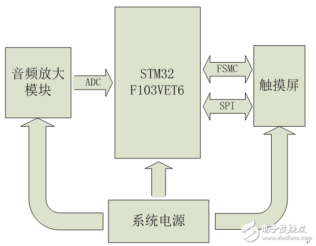
Figure 1.1 Overall structure of the system hardware
1.2.2 MCU selection Traditionally, isolated speech recognition uses speech recognition chips, such as Sunplus SPCE061A, LD3320, etc. Such a scheme is simple in design, short in development cycle, but poor in expandability, generally only recognizes a specific voice, or has a limited number of voice commands. And the price of special chips is generally relatively high, which is unfavorable for system cost control.
STM32F103VET6 is a high performance 32-bit Cortex-M3 core microcontroller from STMicroelectronics with a large number of on-chip ADC, DAC, USB, CAN, SDIO, USART, SPI, IIC, FSMC, RTC, TIM, GPIO, DMA, etc. Peripherals. The Cortex-M3 core belongs to the M series of ARMv7, the latest architecture introduced by ARM, focusing on low cost, low power consumption and high performance. It has a maximum clock speed of 72MHz, 1.25 DMIPS/MHz computing power, a three-stage pipeline with branch prediction, and a single-cycle multiplier and hardware divider. Compared with the ARM7TDMI core, the Cortex-M3 has a significant improvement in performance.
The STM32F103VET6 has three 12-bit 12-channel ADCs with a sampling frequency up to 1MHz. A 12-channel DMA controller that provides access to system Flash, SRAM, and on-chip peripherals to handle memory-to-peripheral, peripheral-to-memory DMA requests. 11 16-bit timers, where T1, T2, T3, T4, T5, and T8 can be connected to the ADC controller to automatically trigger the ADC to initiate an A/D conversion each time a timer capture/compare event arrives. After the A/D conversion is completed, the DMA controller can be automatically triggered to transfer the converted data to the data buffer of the SRAM in sequence. Therefore, the STM32F103VET6 is capable of accurate and efficient A/D conversion. Can meet the needs of audio signal acquisition.
The FSMC (Flexible StaTIc Memory Controller) of the STM32F103VET6 can send the corresponding data/address/control signal type to match the speed of the signal according to different external memory types. The FSMC is connected to the LCD controller and the LCD controller can be configured as an external NOR Flash. When the system needs to access the LCD, it automatically generates the read and write timings that meet the requirements of the LCD controller, and can accurately and quickly complete the control of the LCD interface display. Built-in 3 SPI controllers up to 18Mbit/s, connected to the touch screen controller for touch screen click position detection.
A Chinese voice instruction is collected in the system. The recording time is 2s, and the speech is collected at 8KHz 16bit sampling rate. The required storage space is 32KB. In addition, the RAM space required for intermediate steps such as speech processing, feature extraction and feature matching will not exceed 64KB. The STM32F103VET6 comes with 512KB of Flash and 64KB of RAM. So STM32F103VET6 can be satisfied in the program space. The most time consuming part of speech recognition is the fast Fourier transform in feature extraction. In general, the effective speech time length in isolated speech recognition is less than 1 s. The speech signal is generally 10~30ms for one frame. In this system, the frame is shifted by 20ms, and the frame shift (the overlapping part of two adjacent frames) is 10ms, so that a voice command does not exceed 100 frames. At 8KHz 16bit sampling rate, 20ms is 160 samples. The 16-bit, 1024-point FFT provided by the STM32 firmware library requires only 2.138ms per operation when the core is running at 72MHz. The time required to complete the FFT of 100 frames of data is 213.8 ms. In addition to the time required for other processing, it takes no more than 0.5 s to recognize a voice command. Therefore, STM32F103VET6 can meet the needs in the running time of the program, and can perform real-time isolated speech recognition.
Based on the above argument, the system uses STM32F103VET6 as the master MCU.
1.2.3 Audio signal acquisition scheme Selection Audio signal acquisition uses audio codec chips, such as UDA1341 and VS1003. Such chips offer a wealth of features and system consistency, but they are costly. This system is a low cost solution and only needs to acquire audio signals. Therefore, it is not appropriate to use those dedicated audio codec chips.
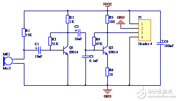
In the audio amplification module of the system, a small microphone is used to complete the acoustic signal conversion, and two 9014 triodes form a two-stage common base amplification circuit. Apply voltage negative feedback to each stage to stabilize the amplification factor.
The frequency band of the speech signal is 300~3400 Hz. According to the sampling theorem, the sampling frequency is set to 8000 Hz, which is enough to complete the acquisition of the speech signal. In this system, TIM1 is set as the ADC trigger source. The TIM clock source is the system clock of 72 MHz. After dividing by 100, it becomes 720KHz. The counting mode is incremented upwards, and the automatic reloading value is 90, that is, the counting value is incremented from 0 to 90 and then returns to 0. If the comparison match value is set to any value between 0 and 90, 8000 compare match events can be issued per second. The ADC performs 8000 A/D conversions per second, ie the sampling frequency is 8KHz.
1.2.4 Display and operation interface Select touch screen as a new input device, which is the simplest, convenient and natural human-computer interaction mode. The LCD touch screen is an inductive liquid crystal display device that can receive a touch click input signal. When touching or tapping the screen, the touch controller can read the location of the touch point so that the user's operation can be directly accepted through the screen. Compared with mechanical buttons, the touch screen is more intuitive and vivid in operation. Comprehensive consideration, this design uses a 2.5 inch 240 × 320 resolution LCD touch screen to achieve interface display and operation.
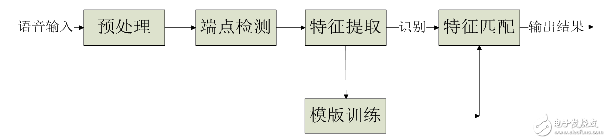
1.3 Algorithm Selection 1.3.1 Software Algorithm General Introduction The pre-processing, endpoint detection, feature extraction, template training, and feature matching of the collected audio signals are processed in some columns, and finally the input speech is recognized.
The system software flow chart is shown below.
1.3.2 Preprocessing Algorithm The preprocessing of selecting speech signals mainly includes: ADC, framing, data windowing, pre-emphasis.
The frequency range of the speech signal is usually 100Hz~3400Hz, because this frequency band contains most of the voice information, which has the greatest meaning for speech recognition. According to the sampling law, to sample the 3400 Hz signal without distortion, the minimum sampling rate required is 6800 Hz. To improve accuracy, commonly used A/D sampling rates range from 8kHz to 12kHz.
Voice signals have an important feature: short-term. Since people are speaking, unvoiced and voiced sounds alternate, and each tone usually lasts only a short period of time. Therefore, from the waveform point of view, the speech signal has a strong "time-varying characteristic". It has a strong periodicity in the voiced passages, noise characteristics in the unvoiced passages, and the characteristics of voiced and unvoiced sounds are constantly changing. As shown in Figure 1.4, its characteristics change over time, so it is an unsteady process. On the other hand, since the formation of speech is closely related to the motion of the vocal organ, this physical motion is slower than the speed of sound vibration (as shown in Figure 1.5). Therefore, in a short time range, its characteristic changes are small or remain unchanged, which can be regarded as a quasi-steady state process. We can analyze and process speech signals using the analytical processing method of the stationary process.
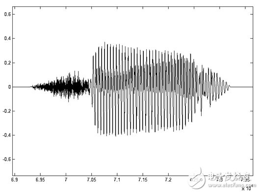
Figure 1.4 Time domain waveform of voice "7"
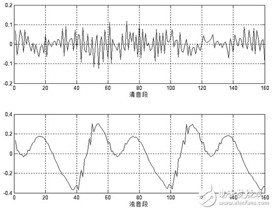
Figure 1.5 20ms short-term waveform of voice "7" unvoiced and voiced segments
Based on the above considerations, the analysis and processing of speech signals must use short-term analysis, that is, framing. The voice signal usually remains relatively stable between 10ms and 30ms. In this design, take 20ms per frame. In order to maintain a smooth transition between the preceding and succeeding frames, the frame shift is 10ms, that is, the overlap between the preceding and succeeding frames is 10ms.
In order to facilitate subsequent speech processing, the framed signal needs to be windowed. The windowing method is as shown in equation (1-1).
![]() (1-1)
(1-1)
Where Y(n) is the windowed signal, y(n) is the input signal, w(n) is the window function, and N is the frame length.
The window function can select a rectangular window, ie
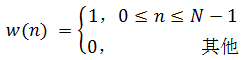
(1-2)
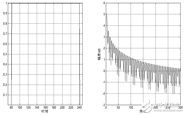
Figure 1.6 Schematic diagram of time domain and frequency domain of rectangular window
Or other form of window function, such as Hamming window
(1-3)
Figure 1.7 Schematic diagram of time domain and frequency domain of Hamming window
The frequency response of these window functions has low-pass characteristics, but different window function shapes will affect the characteristics of the short-term features after the frame. Figure 1.7 and Figure 1.8 show the time and frequency domain diagrams of the 160-point rectangular window and the Hamming window, respectively. It can be seen from the figure that the bandwidth of the Hamming window is approximately twice the bandwidth of the rectangular window of the same width. At the same time, the attenuation of the Hanming window outside the passband is much larger than that of the rectangular window. The main window of the rectangular window is smaller and the side lobes are higher; while the Hamming window has the widest main lobe width and the lowest side lobe height.
For speech signal analysis, the shape of the window function is very important. The spectral smoothness of the rectangular window is good, but the waveform details are easy to lose, and the rectangular window will leak. The Hamming window can effectively overcome the leakage phenomenon, and the application range is also the most extensive. Based on the above discussion, this design uses the Hamming window as a window function. Figure 1.9 and Figure 1.10 show the time-domain and frequency-domain effects of a framed voiced sound plus a rectangular window and a Hamming window, respectively.
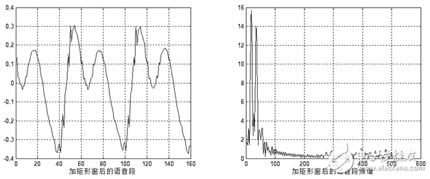
Figure 1.8 Adding a rectangular window
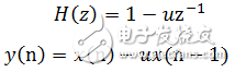
Figure 1.9 Jia Hanming window
Due to the inherent characteristics of human vocal organs, speech will have a 6 dB/octave attenuation from the lips. This effect is mainly manifested in the loss of high-frequency information, which will adversely affect the feature extraction of speech signals. Therefore, the signal must be boosted at a high frequency, that is, the signal is compensated at a high frequency, so that the signal spectrum is flattened for spectral analysis or channel parameter analysis. Pre-emphasis can be achieved with a pre-emphasis digital filter with 6dB/octave boosting high frequency characteristics. The pre-emphasis filter is generally first-order, and its system function and difference equation are as shown in equation (1-4).
(1-4)
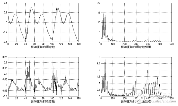
Where y(n) is the boosted output value, and x(n) and x(n-1) are the input values ​​of the current time and the previous time, respectively. u is close to 1, and the typical value is between 0.94 and 0.97. This design takes 0.95. The pre-emphasis effect is shown in Figure 1.11.
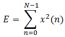
Figure 1.10 Pre-emphasis effect diagram
1.3.3 Endpoint Detection Algorithm Voice Endpoint Detection (VAD), also known as voice activity detection, is mainly used in speech codec, speech recognition and single channel speech enhancement in speech processing. The basic method of speech endpoint detection can be expressed in one sentence: extract one or a series of contrast characteristic parameters from the input signal and compare it to one or a series of threshold thresholds (Figure 3-2). If the threshold is exceeded, it means that there is a segment currently; otherwise it means that it is currently a segmentless. The threshold threshold is usually determined based on the characteristics of the segment. However, this decision process has become very complicated due to the constant changes in speech and environmental noise. Generally, voice endpoint detection is performed on the basis of voice frames, and the length of voice frames varies from 10 ms to 30 ms. A good speech endpoint detection algorithm must have robustness to various noises, while being simple, adaptable, with small delays, and easy to implement in real time.
In the case of high signal-to-noise ratio, the commonly used detection methods generally have the following types: short-time energy, short-time zero-crossing rate. These methods all make use of the characteristic parameters of speech and noise, so the discriminating effect is better. And they are simple to implement, and the amount of calculation is relatively small, so they are widely used.
Short-term energy is defined as follows:
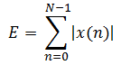 (1-6)
(1-6)
Where N is the frame length and E is the short-term energy value of one frame.
Short-term energy mainly has the following applications: First, short-term energy can distinguish between unvoiced and voiced sounds, because voiced sounds are much larger than unvoiced sounds; secondly, short-term energy can be used to judge voiced and unvoiced segments, and Hyphenation and so on. Short-term energy artificially increases the gap between high and low signals because it squares the signal. More importantly, the result of the square operation is large and it is easy to generate data overflow. An easy way to solve these problems is to use short-term average amplitude values ​​to represent changes in energy. Its definition is as follows:
(1-7)
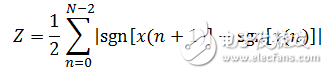
The short-term zero-crossing rate is the simplest feature in the time domain analysis of speech signals. It refers to the number of times a signal passes zero value in each frame, and is defined as follows:
(1-8)
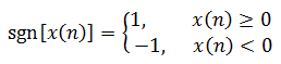
Where sgn(x) is a sign function, ie
(1-9)
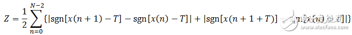
According to the above definition, the unvoiced sound has a high zero-crossing rate because it is similar to white noise. The energy of the voiced sound is concentrated in the low frequency band, so the short-time zero-crossing rate of the voiced signal is low. The short-term zero-crossing rate of noise is higher, mainly because the energy of the speech signal is mainly concentrated in a lower frequency range, and the energy of the noise signal is mainly concentrated in a higher frequency band. The short-time zero-crossing rate thus calculated is susceptible to noise interference. The solution to this problem is to modify the above definition slightly, that is, set a threshold T to modify the meaning of the zero-crossing rate to the number of times across the positive and negative thresholds. The revised definition is as follows:
(1-10)
The short-time zero-crossing rate thus calculated has a certain anti-interference ability. Even if there is random noise, as long as it does not exceed the band formed by the positive and negative thresholds, a false zero-crossing rate will not be generated.
Considering the design needs and system processing capabilities, the design uses short-term amplitude values ​​and improved short-term zero-crossing rates to determine the speech start and end points. The threshold values ​​are set for the short-term amplitude and the short-time zero-crossing rate, respectively. Before each recognition, the first 300ms of the selected speech segment is used as the background noise to determine the two thresholds to achieve adaptive background noise. The specific endpoint detection method is as follows.
Judging the starting point of the voice, it is required to be able to filter out the sudden noise. Sudden noise can cause high values ​​of short-term energy or zero-crossing rate, but often cannot be maintained for a long enough time, such as the switch of doors and windows, the collision of objects, etc., which can be set by setting the shortest time threshold. Discrimination. If one or more of the two thresholds are exceeded and the duration exceeds the effective voice minimum time threshold, return to the point in time when the threshold is exceeded, and mark it as the effective voice start point. Judging the end point of the voice, it is required that the "silent segment" that may be overwhelmed by noise in the middle of the conjunction cannot be discarded. This can be determined by setting the maximum time threshold for the silent segment. At the same time, it is below the two thresholds, and the duration exceeds the silent maximum time threshold, returning to the time point that is initially lower than the threshold, and marking it as the effective speech end point.
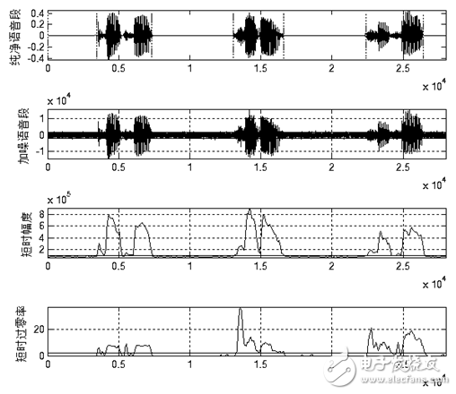
Figure 1.12 and Figure 1.13 show the endpoint detection effects of the above algorithm in the general SNR and low SNR. It can be seen from the figure that the above algorithm can adapt to the general background noise. When the background noise is high, the above algorithm cannot accurately determine the speech start end point. However, after testing, when the signal-to-noise ratio is as low as shown in Figure 1.13, it is difficult for the human ear to accurately recognize the speech. Therefore, the above algorithm can meet the requirements of endpoint detection in actual use.
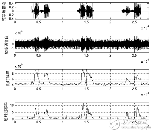
Figure 1.11 Endpoint Detection Effect under General Signal-to-Noise Ratio
![]()
Figure 1.12 Endpoint detection effect at low SNR
1.3.4 Feature Extraction Algorithm Selection In the speech recognition system, the analog speech signal becomes a digital signal after completing the A/D conversion. The speech signal at this time is a signal in the time domain, and the signal in the time domain is difficult to analyze and process, and the amount of data is large. The usual practice is to transform the time domain signal, extract a specific parameter, and perform speech recognition through some parameters that better reflect the essential features of the voice. Feature extraction is a very important part of the recognition process, and the selected features directly affect the recognition results. Different features have different sensitivities to different speech. Excellent speech features should have a larger distance to different words and a smaller distance from the same word.
In addition, the number of eigenvalues ​​is also an important issue. In cases where the requirements for use are met, the number of features used should be minimized to reduce the amount of computation involved. However, too few features may not properly describe the original speech, so that the recognition rate decreases. The method of extracting speech features is the basis of the whole speech recognition, so it has received extensive attention. Through the development of recent decades, the current methods for extracting speech features mainly have the following three categories:
1. Extraction method based on linear predictive analysis. A typical representative of this class is the linear predictive cepstral coefficient LPCC.
2. Extraction method based on spectrum analysis. A typical representative of this class is the Mel frequency cepstral coefficient MFCC.
3. Feature analysis methods based on other digital signal processing techniques. Such as wavelet analysis, time-frequency analysis, artificial neural network analysis.
Most of the current isolated speech recognition systems use the first two speech feature extraction methods. In this paper, we draw on the previous comparison of LPCC coefficient and MFCC coefficient, and use the Mel frequency cepstrum coefficient MFCC.
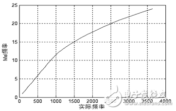
The human cochlea is essentially equivalent to a filter bank. The filtering effect of the cochlea is linear scale below 1000 Hz, and the logarithmic scale above 1000 Hz, which makes the resolution of the human ear to low frequency signals higher than that of high frequency signals. rate. Based on this characteristic, the researchers obtained a set of filter banks similar to the cochlear effect based on psychological experiments. This is the Mel frequency filter bank. The Mel frequency can be expressed by the following formula:
(1-11)
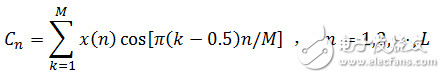
Figure 1.13 Correspondence between Mel frequency and actual frequency
The uneven division of the frequency axis is the most important feature of the MFCC feature that is distinguished from the ordinary cepstrum feature. After transforming the frequency into the Mel domain according to Equation (1-11) and Figure 1.13, the center frequency of the Mel bandpass filter bank is evenly arranged according to the Mel frequency scale. In this design, the calculation process of the MFCC cepstral coefficient is as follows.
1. Pre-emphasis, framing, and Hanming window processing of the speech signal, and then performing short-time Fourier transform to obtain the spectrum.
2. Take the square of the spectrum and get the energy spectrum. And filtering with 24 Mel-triangle bandpass filters; since the components of each frequency band are superimposed in the human ear, the energy in each filter band is superimposed, and the Mel power spectrum is output.
3. Logarithmically the output value of each filter to obtain the logarithmic power spectrum of the corresponding frequency band. Then, the inverse discrete cosine transform is performed on 24 logarithmic powers to obtain 12 MFCC coefficients, and the inverse discrete cosine transform is as shown in equation (1-12), where M=24 and L=12.
(1-12)
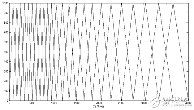
In this design, the sampling frequency of the collected speech signal is 8000 Hz, and the frequency range is 0 Hz to 4000 Hz. The Mel triangle bandpass filter bank in this frequency range is shown below:
![]()
Figure 1.14 Mel Triangle Filter Bank
Compared with the LPCC parameters, the MFCC parameters have the following advantages:
1. Most of the speech information is concentrated in the low frequency part, while the high frequency part is susceptible to environmental noise. The MFCC parameter converts the linear frequency scale to the Mel frequency standard. Emphasizes the low-frequency information of the speech, thereby highlighting the information that is conducive to identification, shielding the interference of noise.
2. The MFCC parameters have no assumptions and can be used in a variety of situations. The LPCC parameters need to assume that the processed signal is an AR signal. For consonants with strong dynamic characteristics, this assumption is not strictly established.
Therefore, the anti-noise characteristics of the MFCC parameters are superior to the LPCC parameters. In this design, the speech feature parameters used are all MFCC parameters.
1.3.5 Feature Matching Algorithm Selection It is not enough to establish a good speech recognition system with good speech characteristics. It is also necessary to have appropriate speech recognition models and algorithms. At this stage, the process of speech recognition is based on the principle of pattern matching, and calculates the distance measure between the unknown speech mode and each template in the speech template library, so as to obtain the best matching mode. At present, the model matching methods applied by speech recognition mainly include dynamic time warping (DTW: Dynamic Time Warping), Hidden Markov Model (HMM) and artificial neural network (ANN: Artificial Neural Networks). The most commonly used recognition algorithms in the field of isolated word recognition are DTW and HMM.
The DTW algorithm is an early pattern matching and model training technique. It uses the dynamic programming method to successfully solve the problem of different time durations of speech signal feature parameter comparison, and obtains good performance in isolated speech recognition. The DTW algorithm is based on the theory of dynamic programming (DP: Dynamic Programming). Dynamic programming is a very effective way to find the best solution to a problem. The central idea can be described as simple: on an optimal path, any one of the sub-paths must also be the best path for the relevant sub-problem, otherwise the original path is not the best path.
The HMM algorithm is a kind of important double stochastic model in mathematics. The method of probabilistic statistics is used to describe time-varying speech signals, which describes the overall non-stationarity and local stationarity of speech signals. Each state of the HMM corresponds to each stationary segment of the speech signal, and each state is associated with a certain transition probability, which is an ideal speech model. The HMM model belongs to statistical speech recognition and is suitable for large vocabulary and non-specific speech recognition systems. With the rapid development of modern computer technology, the computing speed of computers has increased rapidly, and the hidden Markov model analysis method has also been widely used. The algorithm has less computational complexity and strong adaptability in the identification stage, but it requires a lot of preliminary training work and requires more system resources.
For isolated word recognition, the recognition effect of DTW algorithm and HMM algorithm is similar under the same environmental conditions, but the HMM algorithm is much more complicated. This is mainly reflected in the fact that HMM algorithm needs to provide a large amount of voice data during the training phase. The calculation can get the model parameters, and the training of the DTW algorithm requires almost no additional calculations. Therefore, in isolated speech recognition, DTW algorithm is more widely used.
The comprehensive comparison of the DTW algorithm has a small workload and does not require a large amount of voice data, and the DTW algorithm is suitable for isolated speech recognition, and is easy to implement, saves system resources, and is more convenient to transplant into an embedded system. Therefore, the system chooses DTW algorithm as the core algorithm of speech recognition. The following describes the DTW algorithm and its implementation.
Assuming that the feature vector sequence of the reference template is, the input speech feature vector sequence is ![]() , input speech feature vector sequence is
, input speech feature vector sequence is ![]() . The DTW algorithm is to find an optimal time warping function, so that the time axis j of the speech to be tested is nonlinearly mapped to the time axis i of the reference template, so that the total accumulated distortion amount is minimized.
. The DTW algorithm is to find an optimal time warping function, so that the time axis j of the speech to be tested is nonlinearly mapped to the time axis i of the reference template, so that the total accumulated distortion amount is minimized.
Let the time warping function be
![]() (1-13)
(1-13)
Where N is the matching path length, ![]() It is indicated that the nth matching point is the i(n)th feature vector of the reference template and the jth (n)th feature vector of the template to be tested. Distance between the two
It is indicated that the nth matching point is the i(n)th feature vector of the reference template and the jth (n)th feature vector of the template to be tested. Distance between the two ![]() Called the local matching distance. The DTW algorithm achieves a minimum sum of matching distances by means of local optimization.
Called the local matching distance. The DTW algorithm achieves a minimum sum of matching distances by means of local optimization.
The general time warping function satisfies the following constraints:
1. Monotonic, the regular function increases monotonously.
2. Starting point and ending point constraints, starting point to starting point, ending point to ending point.
3. Continuity, it is not allowed to skip any point.
4. The maximum regularity does not exceed a certain limit.
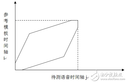
M is the window width. The area where the regular function is located is located in the parallelogram. In this design, the end point of the constraint area of ​​the parallelogram is relaxed by 3 points. Local path constraints are used to limit the number of possible paths in the last few steps when the nth step. The DTW regular area and local path in this design are shown in Figure 1.16 and Figure 1.17.
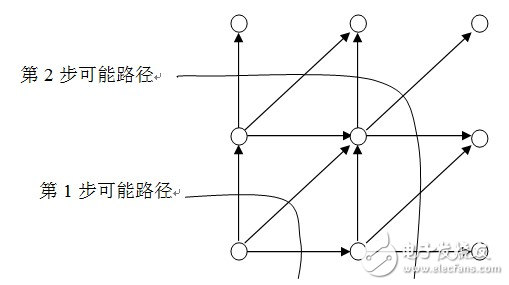
Figure 1.15 Relaxing the DTW regular area of ​​the endpoint limit
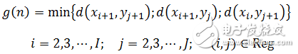
Figure 1.16 DTW local path
The calculation steps of the DTW algorithm in this design:
1. Initialization. Let i(0)=j(0)=0, i(N)=I,j(N)=J, determine a regular constraint region Reg as shown in Figure 1.16. It is derived from a parallelogram. This parallelogram has two vertices at (1,1) and (I,J), and the slopes of the adjacent two sides are 2 and 1/2, respectively.
2. Recursively calculate the matching distance according to the path shown in Figure 1.17. The nth step matching distance is as follows
(1-14)
3. The cumulative matching distance is divided by the number of matching steps, and the normalized matching distance is obtained. That is, the matching distance between the input feature and the feature template. The matching distance between the input feature and each feature template is calculated, and the feature template with the smallest matching distance has the greatest similarity with the input feature.
Chapter 2 System Design 2.1 Hardware Design 2.1.1 MCU and its minimum system circuit design After the first chapter of the demonstration, choose STMicroelectronics' STM32F103VET6 microcontroller.
The MCU input clock is provided by an 8MHz crystal and is multiplied to 72MHz by the MCU's internal PLL. A 0.1uF decoupling capacitor is connected to each power supply pin to improve the stability and immunity of the MCU power supply.
2.1.2 Audio signal acquisition circuit design The schematic diagram of the audio signal acquisition circuit is as follows

Figure 2.6 Audio signal acquisition schematic
2.1.3 LCD interface circuit design In this design, the display device uses a 2.4-inch TFT LCD display, and the LCD driver is ILI9325.
Thin Film Transistor means that each liquid crystal pixel on a liquid crystal display is driven by a thin film transistor integrated thereafter. Thus, high-speed, high-brightness, high-contrast display screen information can be achieved.
The ILI9325 is a 262144 color single-chip TFT LCD SoC driver. It provides 240 x 320 resolution, 172,800 bytes of graphics data RAM, and an internal power supply circuit. Its interface with the controller can be set to 16-bit parallel port, 8-bit parallel port, SPI interface. In order to improve the transmission rate of display data in this design, the 16-bit parallel port of the FSMC (Variable Static Memory Controller) of STM32F103VET6 is used as the interface between the MCU and the ILI9325. Map the ILI9325's data and control interfaces to external memory. When the MCU transmits control commands or displays data, it automatically generates corresponding timings, which avoids the traditional use of IO port analog timing and improves data transmission efficiency.
2.2 Software Design 2.2.1 Speech Preprocessing Algorithm The design of speech signal preprocessing includes: speech signal acquisition, framing, data windowing, pre-emphasis.
Speech signal acquisition is the process of converting an externally simulated speech signal into a digital signal that the MCU can process and recognize. In this design, the digitization of the input speech signal of the audio signal acquisition module is realized by the timer, the analog-to-digital converter and the DMA controller inside the MCU. The processing flow is shown in the figure below.
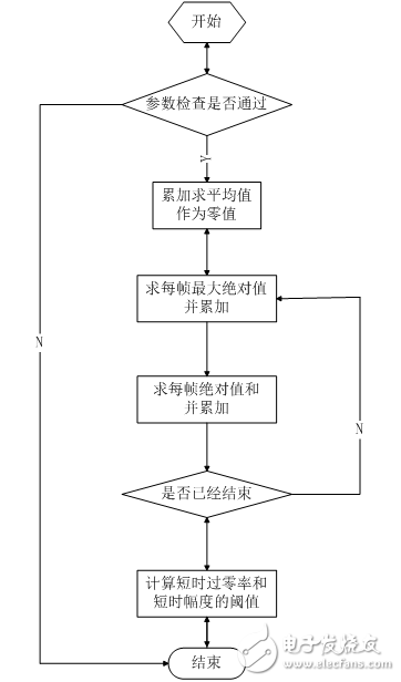
Figure 2.9 Speech signal digitization flow chart
In the program, the function that controls the acquisition of the speech signal is as follows.
1void record(void)
2{
3 delay_ms(atap_len_t); //delay, avoiding noise from tapping the screen
4 TIM_Cmd (TIM1, ENABLE); / / start the timer, start signal acquisition
5 GUI_ClrArea(&(Label[G_ctrl])); //Show action prompts
6
7 GUI_DispStr(&(Label[G_ctrl]), "recording");
8 delay_ms(atap_len_t); // Record a small background sound before starting to talk to achieve background noise adaptation
9 //Prompt to start talking
10 set_label_backclor(&(Label[G_spk]), spk_clor);
11 //waiting for the buffer data to be updated
12 while(DMA_GetFlagStatus(DMA1_FLAG_TC1)==RESET);
13 TIM_Cmd(TIM1, DISABLE); //End of data acquisition, close timer
14 DMA_ClearFlag(DMA1_FLAG_TC1); // Clear data transfer completion flag for next use
15 //Prompt to start processing the collected data
16 set_label_backclor(&(Label[G_spk]), prc_clor);
17}
Framing is the process of dividing the collected speech data into segments of the same length for short-term analysis. In this design, 20ms or 160 points is taken as one frame, and the frame is shifted by 10ms or 80 points.为了适应MCUå˜å‚¨ç©ºé—´æœ‰é™çš„实际情况,分帧并没有被å•ç‹¬è®¾è®¡å’Œå 用å•ç‹¬çš„空间,而是在读è¯éŸ³æ•°æ®ç¼“冲区的时候按照帧长帧移的顺åºä¾æ¬¡è¯»å–。
由于端点检测属于时域分æžï¼Œå¹¶ä¸éœ€è¦åŠ çª—å’Œé¢„åŠ é‡ï¼Œæ‰€ä»¥æœ¬è®¾è®¡ä¸ï¼Œåˆ†å¸§å’Œé¢„åŠ é‡éƒ½åŠ 在端点检测之åŽæå–MFCC之å‰ã€‚
2.2.2 端点检测算法设计本设计采用çŸæ—¶å¹…度和çŸæ—¶è¿‡é›¶çŽ‡ç›¸ç»“åˆçš„端点检测算法。
首先去缓冲区å‰300ms作为背景噪声,æå–背景噪声å‚数。用于åŽç»ç«¯ç‚¹æ£€æµ‹ã€‚背景噪声å‚数由以下结构体定义。
1typedef struct
2{
3 u32 mid_val; //è¯éŸ³æ®µä¸å€¼ç›¸å½“于有符å·çš„0值用于çŸæ—¶è¿‡é›¶çŽ‡è®¡ç®—
4 u16 n_thl; //噪声阈值,用于çŸæ—¶è¿‡é›¶çŽ‡è®¡ç®—
5 u16 z_thl; //çŸæ—¶è¿‡é›¶çŽ‡é˜ˆå€¼ï¼Œè¶…过æ¤é˜ˆå€¼ï¼Œè§†ä¸ºè¿›å…¥è¿‡æ¸¡æ®µã€‚
6 u32 s_thl; //çŸæ—¶ç´¯åŠ 和阈值,超过æ¤é˜ˆå€¼ï¼Œè§†ä¸ºè¿›å…¥è¿‡æ¸¡æ®µã€‚
7}atap_tag; //自适应å‚æ•°
æå–函数为void noise_atap(const u16* noise,u16 n_len,atap_tag* atap),其æå–过程如下。
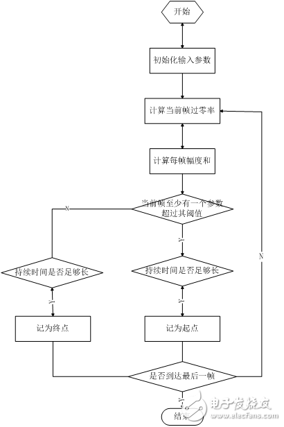
图2.10 背景噪声å‚æ•°æå–æµç¨‹
然åŽæ ¹æ®æå–到的çŸæ—¶è¿‡é›¶çŽ‡å’ŒçŸæ—¶å¹…度计算有效è¯éŸ³èµ·å§‹å’Œç»“æŸç‚¹ã€‚有效è¯éŸ³ç«¯ç‚¹ç”±ä»¥ä¸‹ç»“构体定义。
1typedef struct
2{
3 u16 *start; //起始点
4 u16 *end; //结æŸç‚¹
5}valid_tag; //有效è¯éŸ³æ®µ
端点检测函数为void VAD(const u16 *vc, u16 buf_len, valid_tag *valid_voice, atap_tag *atap_arg)。其æµç¨‹å›¾å¦‚下。
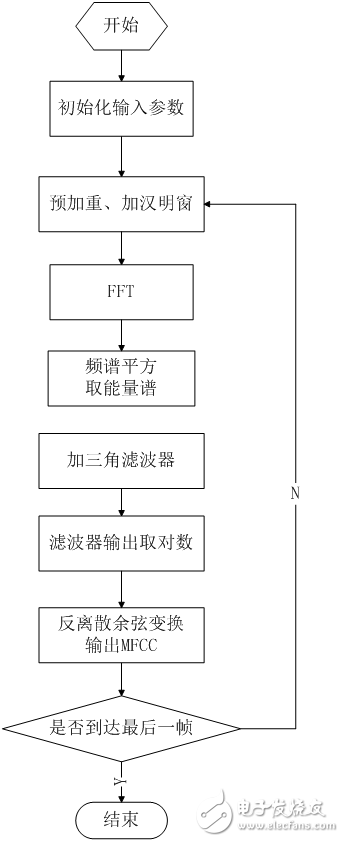
图2.11 端点检测æµç¨‹
2.2.3 特å¾æå–算法设计åŠä¼˜åŒ–本设计选用12阶MFCC作为è¯éŸ³ç‰¹å¾ã€‚æ¤æ¥æ˜¯æ•´ä¸ªç®—法æµç¨‹ä¸æœ€è€—æ—¶ä¹Ÿæ˜¯ä¼˜åŒ–ç©ºé—´æœ€å¤§çš„éƒ¨åˆ†ã€‚å› æ¤ï¼Œåœ¨ç¨‹åºè®¾è®¡ä¸ï¼Œæ²¿ç”¨ç»å…¸ç®—法的åŒæ—¶åšäº†å¤§é‡çš„针对STM32嵌入å¼å¹³å°çš„优化工作。优化的ä¸å¿ƒæ€æƒ³æ˜¯ï¼šå°½é‡å°‘使用或ä¸ä½¿ç”¨æµ®ç‚¹è¿ç®—;使用整型数,其è¿ç®—结果应尽é‡å¤§ä»¥å‡å°‘èˆå…¥å™ªå£°ï¼Œä½†å¿…é¡»ä¿è¯æ•°æ®ä¸ä¼šæº¢å‡ºï¼›ç©ºé—´æ¢æ—¶é—´ã€‚
FFT函数是u32* fft(s16* dat_buf, u16 buf_len)。它å°è£…了了STæ供的STM32固件库里的void cr4_fft_1024_stm32(void *pssOUT, void *pssIN, u16 Nbin)函数。cr4_fft_1024_stm32()输入å‚数是有符å·æ•°ï¼ŒåŒ…括实数和虚数,但è¯éŸ³æ•°æ®åªåŒ…括实数部分,虚数用0填充,fft点数超出输入数æ®é•¿åº¦æ—¶ï¼Œè¶…过部分用0填充。cr4_fft_1024_stm32()输出数æ®åŒ…括实数和虚数,应该å–å…¶ç»å¯¹å€¼ï¼Œå³å¹³æ–¹å’Œçš„æ ¹ã€‚
è¯éŸ³ç‰¹å¾ç”¨å¦‚下结构体定义。
1typedef struct
2{
3 u16 save_sign; //å˜å‚¨æ ‡è®°ç”¨äºŽåˆ¤æ–flashä¸ç‰¹å¾æ¨¡æ¿æ˜¯å¦æœ‰æ•ˆ
4 u16 frm_num; //帧数
5 s16 mfcc_datï¼»vv_frm_max*mfcc_numï¼½; //MFCC转æ¢ç»“æžœ
6}v_ftr_tag;
获å–MFCC的函数是void get_mfcc(valid_tag *valid, v_ftr_tag *v_ftr, atap_tag *atap_arg)。获å–MFCC的一般æ¥éª¤åœ¨ä¸Šä¸€ç« 已有论述,在æ¤ä»‹ç»ç§»æ¤åˆ°MCU上需åšçš„优化。
é¢„åŠ é‡çš„高通滤波系数为0.95,如果直接使用,则需è¦è¿›è¡Œæµ®ç‚¹è¿ç®—,尽é‡é¿å…,故使用y(n)=x(n)-x(n-1)×95/100ã€‚åŠ æ±‰æ˜Žçª—çª—å‡½æ•°å€¼å¦‚æžœæ¯æ¬¡éƒ½è¦é‡æ–°è®¡ç®—,则需è¦è¿›è¡Œä¸‰è§’函数è¿ç®—,耗时严é‡ï¼Œæ•ˆçŽ‡ä½Žä¸‹ã€‚ä½†å…¶æ•°å€¼æ˜¯ä¸€å®šçš„ï¼Œå› æ¤äº‹å…ˆè®¡ç®—好160点的汉明窗值。å˜äºŽæ•°ç»„ä¸const u16 hamm[],使用时直接读å–。FFT函数直接输入ADC转æ¢è¿‡çš„值-2048~2047,其输出频谱幅值过å°ï¼Œèˆå…¥è¯¯å·®è¾ƒå¤§ã€‚æ•°æ®è¾“å…¥å‰éœ€ä½œæ”¾å¤§å¤„ç†ã€‚vc_tempï¼» iï¼½=(s16)(temp*hammï¼» iï¼½/(hamm_top/10));æ¤å¥ä»£ç åœ¨å®žçŽ°åŠ çª—çš„åŒæ—¶ï¼Œå°†è¯éŸ³æ•°æ®æ”¾å¤§10å€ã€‚Mel三角滤波器的ä¸å¿ƒé¢‘率和数值的计算涉åŠåˆ°å¯¹æ•°è¿ç®—,ä¸å®œç›´æŽ¥è®¡ç®—,也实现计算好的数值å˜äºŽFlashä¸ï¼Œä½¿ç”¨æ—¶ç›´æŽ¥è¯»å–。还有其他的优化措施,详è§é™„件代ç 。
void get_mfcc(valid_tag *valid, v_ftr_tag *v_ftr, atap_tag *atap_arg)函数æµç¨‹å¦‚下。
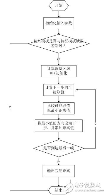
图2.12 特å¾æå–æµç¨‹
2.2.4模æ¿è®ç»ƒç®—法设计
本设计模æ¿è®ç»ƒé‡‡ç”¨å†—余模æ¿ç®—法,å³æ¯ä¸ªè¯éŸ³æŒ‡ä»¤å˜å‚¨4个特å¾æ¨¡æ¿ï¼Œè¯†åˆ«æ—¶è¾“入特å¾åˆ†åˆ«ä¸Žæ¯ä¸ªç‰¹å¾æ¨¡æ¿ç›¸æ¯”较,匹é…è·ç¦»æœ€å°çš„,就是识别结果。这4个特å¾æ¨¡æ¿å˜å‚¨äºŽMCU FlashåŽç«¯ï¼Œæ¨¡æ¿è®ç»ƒæ—¶ï¼Œå°†æ¨¡æ¿å˜äºŽæŒ‡å®šçš„Flash地å€ã€‚为了ä¿è¯ä¿å˜çš„特å¾æ¨¡æ¿ä¸è¢«æ“¦é™¤æˆ–被其他代ç 或数æ®å 用,需设置编译器的地å€èŒƒå›´ã€‚
2.2.5特å¾åŒ¹é…算法设计
本设计特å¾åŒ¹é…算法采用DTW(动æ€æ—¶é—´å¼¯æŠ˜ï¼‰ã€‚其原ç†åœ¨ä¸Šä¸€ç« 已有论述,在æ¤ä¸å†èµ˜è¿°ã€‚å…¶æµç¨‹å¦‚下。

图2.13 特å¾åŒ¹é…æµç¨‹
2.2.6显示界é¢è®¾è®¡æœ¬è®¾è®¡åœ¨è§¦æ‘¸å¼LCD上实现了简å•çš„GUIæ“作界é¢ã€‚能够显示ä¸è‹±æ–‡æ–‡æœ¬æ¡†ã€æŒ‰é’®ã€‚
æœ€åŸºæœ¬å…ƒç´ ä¸ºGUI_Area,定义如下。
1typedef struct
2{
3 u16 Left; //区域离å±å¹•å·¦è¾¹ç•Œçš„è·ç¦»åƒç´
4 u16 Top; //区域离å±å¹•ä¸Šè¾¹ç•Œçš„è·ç¦»åƒç´
5 u16 Width; //区域宽度åƒç´
6 u16 Height; //区域高度åƒç´
7 u16 BackColor; //区域背景色
8 u16 ForeColor; //区域å‰æ™¯è‰²
9}GUI_Area;
在æ¤åŸºç¡€ä¸Šå®žçŽ°äº†ä»¥ä¸‹å‡½æ•°ã€‚
1void wait_touch(void); //ç‰å¾…å±å¹•ç‚¹å‡»
2u8 touch_area(GUI_Area *area); //判æ–是å¦ç‚¹å‡»æŒ‡å®šåŒºåŸŸ
3void GUI_HideArea(GUI_Area *Area); //éšè—区域显示å±å¹•å‰æ™¯è‰²
4void GUI_ClrArea(GUI_Area *Area); //清除区域显示区域背景色
5void GUI_DispStr(GUI_Area *Area,const u8 *str); //在区域内显示å—符串
6void GUI_printf(GUI_Area *Area,char *fmt, 。。。); //printf函数在区域内的实现
é…åˆæ˜¾ç¤ºç•Œé¢ï¼Œä¸»å‡½æ•°æµç¨‹å¦‚下。
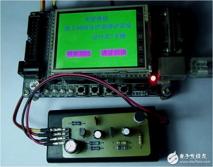
图2.14 主程åºæµç¨‹
ç¬¬ä¸‰ç« ç³»ç»Ÿåˆ¶ä½œåŠè°ƒè¯•ç»“æžœ3.1系统制作与调试本系统的制作调试主è¦åˆ†ä¸ºMatlab仿真ã€ç¡¬ä»¶è°ƒè¯•ã€è½¯ä»¶è°ƒè¯•ã€‚
ç»è¿‡åˆæ¥çš„分æžè®¾è®¡åŽï¼ŒMatlabä¸ä»¿çœŸç®—法。调节算法细节,直至能够较好地实现所需功能,å†å°†å…¶ç§»æ¤åˆ°MCUå¹³å°ä¸Šã€‚在设计制作硬件电路的åŒæ—¶ï¼Œè°ƒè¯•ç©¿æ’进行,应用系统的硬件调试和软件调试是分ä¸å¼€çš„,许多硬件故障是在调试软件时æ‰å‘现的。但通常是先排除系统ä¸æ˜Žæ˜¾çš„硬件故障åŽæ‰å’Œè½¯ä»¶ç»“åˆèµ·æ¥è°ƒè¯•ï¼Œå¦‚æ¤æœ‰åˆ©äºŽé—®é¢˜çš„分æžå’Œè§£å†³ï¼Œä¸ä¼šé€ æˆé—®é¢˜çš„积累,从而å¯ä»¥èŠ‚约大é‡çš„调试时间。软件编程ä¸ï¼Œé¦–先完æˆå•å…ƒåŠŸèƒ½æ¨¡å—的调试,然åŽè¿›è¡Œç³»ç»Ÿè°ƒè¯•ï¼Œæ•´ä½“上采用硬件调试的调试方法。
3.2制作与调试结果ç»è¿‡åˆ¶ä½œä¸Žè°ƒè¯•ï¼Œå®žçŽ°äº†ç³»ç»Ÿé¢„设功能。实物图如下。
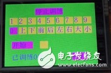
图3.1 实物图欢迎界é¢
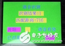
图3.2 实物图模æ¿è®ç»ƒç•Œé¢
图3.3 实物图è¯éŸ³è¯†åˆ«ç•Œé¢
结论原ç†æ ·æœºç»è¿‡è®¾è®¡æ–¹æ¡ˆè®ºè¯ï¼Œè®¾è®¡äº†ç›¸åº”的硬件电路和系统软件,制作了电路原ç†æ ·æœºå¹¶è¿›è¡Œå•æœºè°ƒè¯•ï¼Œç»“果表明,所设计的电路和软件能完æˆåŸºæœ¬çš„测试功能。
采用STM32F103VET6å•ç‰‡æœºæž„建è¯éŸ³è¯†åˆ«ç³»ç»Ÿï¼Œé€šè¿‡æ¤ç³»ç»Ÿå¯¹è¯éŸ³ä¿¡å·è¿›è¡Œé‡‡é›†ã€å‰ç«¯æ”¾å¤§ã€AD转æ¢ã€é¢„处ç†ã€MFCC特å¾æå–ã€æ¨¡æ¿è®ç»ƒã€DTW特å¾åŒ¹é…的一系列æ¥éª¤ï¼Œå®Œæˆå¤ç«‹è¯è¯éŸ³è¯†åˆ«çš„é¢„æœŸç›®æ ‡ã€‚
本设计目å‰ä¹Ÿå˜åœ¨ä¸€äº›ä¸è¶³ï¼Œä¾‹å¦‚è¯éŸ³ä¿¡å·é‡‡é›†æ¨¡å—的动æ€èŒƒå›´ä¸è¶³ï¼Œå½“说è¯å£°éŸ³è¾ƒå¤§æˆ–较å°æ—¶ï¼Œä¼šå‡ºçŽ°æ— æ³•è¯†åˆ«çš„çŽ°è±¡ï¼Œéœ€åŠ ä¸Šè‡ªåŠ¨å¢žç›ŠæŽ§åˆ¶åŠŸèƒ½ã€‚è¯éŸ³è¯†åˆ«æ—¶ï¼Œå½•éŸ³æŽ§åˆ¶ä¸æ–¹ä¾¿ï¼Œæœ€å¥½èƒ½å¤Ÿæ”¹è¿›ä¸ºå®Œå…¨é€šè¿‡è¯éŸ³æŽ§åˆ¶ã€‚特å¾æ¨¡æ¿ä»…仅用12阶MFCC略显ä¸è¶³ï¼Œå¯æ·»åŠ MFCC一阶差分。
å‚考文献[1ï¼½ 韩纪庆ã€å¼ 磊ã€éƒ‘é“然。 è¯éŸ³ä¿¡å·å¤„ç†ã€‚ 北京:清åŽå¤§å¦å‡ºç‰ˆç¤¾ï¼»M],2004å¹´9月
ï¼»2ï¼½ 董辰辉ã€å½é›ªå³°ã€‚ MATLAB 2008 全程指å—。 北京:电å工业出版社[M],2009å¹´3月
ï¼»3ï¼½ å¼ é›ªè‹±ã€‚ æ•°å—è¯éŸ³å¤„ç†åŠMATLAB仿真。 北京:电å工业出版社[M],2011å¹´7月
ï¼»4ï¼½ 赵力。 è¯éŸ³ä¿¡å·å¤„ç†ç¬¬2版。 北京:机械工业出版社[M],2011å¹´6月
ï¼»5ï¼½ 陈程。 机载环境下的è¯éŸ³è¯†åˆ«æŠ€æœ¯åŠå®žçŽ°ï¼»J]。电å科技大å¦ç¡•å£«å¦ä½è®ºæ–‡ï¼Œ2008å¹´5月
ï¼»6ï¼½ è’‹å云。 基于ARM嵌入å¼å¤ç«‹è¯è¯éŸ³è¯†åˆ«ç³»ç»Ÿç ”究与实现[J]。 ä¸å—大å¦ç¡•å£«å¦ä½è®ºæ–‡ï¼Œ 2009å¹´5月
ï¼»7ï¼½ 白顺先。 汉è¯å¤ç«‹å—è¯éŸ³è¯†åˆ«æŠ€æœ¯çš„ç ”ç©¶ï¼»J]。 西å—交通大å¦ç¡•å£«å¦ä½è®ºæ–‡ï¼Œ 2009å¹´6月
ï¼»8ï¼½ 童红。 å¤ç«‹è¯è¯éŸ³è¯†åˆ«ç³»ç»Ÿçš„æŠ€æœ¯ç ”ç©¶ï¼»J]。 江è‹å¤§å¦ç¡•å£«å¦ä½è®ºæ–‡ï¼Œ 2009å¹´6月
ï¼»9ï¼½ 汪冰。 å°è¯æ±‡éžç‰¹å®šäººçš„å¤ç«‹è¯è¯éŸ³è¯†åˆ«ç³»ç»Ÿçš„ç ”ç©¶ä¸Žè®¾è®¡ï¼»J]。 广东工业大å¦ç¡•å£«å¦ä½è®ºæ–‡ï¼Œ 2008å¹´5月
ï¼»10ï¼½ 黄振åŽã€‚ å¤ç«‹è¯è¯†åˆ«ä¸çš„说è¯äººå½’一化技术[J]。 上海大å¦ç¡•å£«å¦ä½è®ºæ–‡ï¼Œ 2009å¹´1月
å¼€æº
/********* main.C **********/
#include “includes.hâ€
#include “VAD.Hâ€
#include “MFCC.Hâ€
#include “DTW.Hâ€
#include “GUI.Hâ€
#include “flash.hâ€
#include “delay.hâ€
u16 VcBufï¼»VcBuf_Lenï¼½;
atap_tag atap_arg;
valid_tag valid_voiceï¼»max_vc_conï¼½;
v_ftr_tag ftr;
typedef struct
{
u8 strï¼»3ï¼½;
}comm_tag;
comm_tag commstr[]={“0 â€ï¼Œâ€œ1 â€ï¼Œâ€œ2 â€ï¼Œâ€œ3 â€ï¼Œâ€œ4 â€ï¼Œâ€œ5 â€ï¼Œâ€œ6 â€ï¼Œâ€œ7 â€ï¼Œâ€œ8 â€ï¼Œâ€œ9 â€ï¼Œâ€œä¸Šâ€ï¼Œâ€œä¸‹â€ï¼Œâ€œå‰â€ï¼Œâ€œåŽâ€ï¼Œâ€œå·¦â€ï¼Œâ€œå³â€ï¼Œâ€œå¤§â€ï¼Œâ€œå°â€};
#define sel_clor BRED
#define dis_sel_clor GRED
#define spk_clor BRED
#define prc_clor GRED
#define save_ok 0
#define VAD_fail 1
#define MFCC_fail 2
#define Flash_fail 3
void disp_comm(u8 comm)
{
GUI_ClrArea(&(Label[comm]));
GUI_DispStr(&(Label[comm]),(u8 *)(commstr[comm-G_comm_fst].str));
}
void set_comm_backclor(u8 comm, u16 backclor)
{
Labelï¼»commï¼½.BackColor=backclor;
disp_comm(comm);
}
void set_label_backclor(GUI_Area *Label, u16 backclor)
{
Label-》BackColor=backclor;
GUI_ClrArea(Label);
}
void disp_home(v
High temperature wire, high temperature resistant wire, please don't take the safety of electricity as a bet, but the quality and credibility of your own products as a bet. If you want to find a regular cable, and find a regular manufacturer, our cables are instantly conductive, stronger and safer than others, refreshing your imagination of materials. We will spend a lifetime of continuous improvement, just to achieve the real environmental protection level of materials and reduce carcinogens. Only for health, a truly environmentally friendly material. Safety check, every product has been tested. High-precision wires have lower resistance, lower heat, and lasting and stable conductivity. Real-time monitoring of wire eccentricity and outer diameter to ensure uniform thickness of insulation layer and sheath. Eliminate the addition of heavy metals and non-environmentally friendly substances such as lead, mercury and other harmful substances. Does not contain any harmful substances to avoid adverse effects on the human body and the environment.
We eliminate mold costs and save money for customers by providing hundreds of thousands of inventory overmolding. For highly customized molded cable manufacturing projects, our advanced technology allows us to produce custom overmoldings at a price and quality level that clearly sets us ahead of our competitors.
Custom molded wire assembly, overmolded IP67/68 connectors assembling,customized waterproofing cable assembly
ETOP WIREHARNESS LIMITED , https://www.wireharness-assembling.com