The customer requested to detect the time from when the relay was energized to closing, and specially called the customer service call to the technical support department of Haiwell to consult the solution. According to customer requirements, we know that the relay pull-in action generally goes through the following processes:
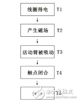
Among them, T1 and T2 are electrical actions, and the time is negligible; T4 and T5 are mechanical actions, the coil must overcome the spring force, and finally we find the time T:

From a theoretical analysis, the pull-in time of about 10ms for the relay is relatively fast, and the ordinary relay will reach tens of milliseconds. But if based on the calculation formula, we can neither provide an accurate measurement of the distance before the contact nor know the action speed of the relay in a short time, then, do we have no way to measure it? Of course not, the following is the solution.
solution:
The pull-in time of the relay is fast. If a general timer is used to calculate the pull-in time, the error is relatively large. Haiwell PLC provides a 16us system clock, which is the system register SV49SV50, which automatically adds 1 every 16us register.
To solve the problem of high-precision timing, we also need to have fast response capabilities. Haiwell's full range of PLC switch input X0-X7 provides rising and falling edge capture interrupts respectively. The interrupts are not affected by the PLC scan cycle and can achieve fast response.
Hardware wiring:
According to customer requirements and solutions, we simply draw the wiring diagram as follows:
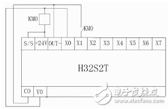
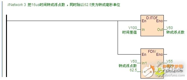
We use the Y0 output of the PLC to drive the relay coil KM0, and at the same time connect the Y0 output signal to X0, trigger the X0 rising edge interrupt, and record the time of SV49SV50 at this time. When the relay is closed, the normally open contact becomes normally closed. At this time, the X1 rising edge interrupt is triggered. Record the time of SV49SV50 at this time in the interrupt program. Subtract the time of SV49SV50 recorded twice to get the time from power-on to pull-in of the relay. Finally, take this The time interval in units of 16us, converted into milliseconds, can get the closed high-precision time value.
Programming:
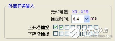
First, check the edge interrupt in the hardware configuration of Haiwell PLC programming software, as shown in the following figure:
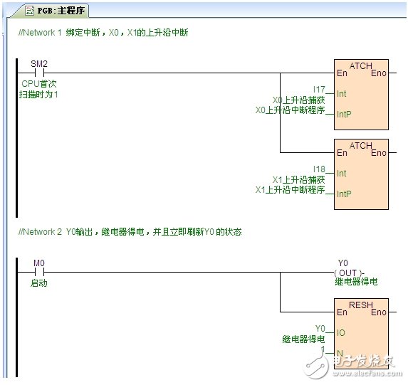
Main program: bind interrupts, and do multiple measurement data records
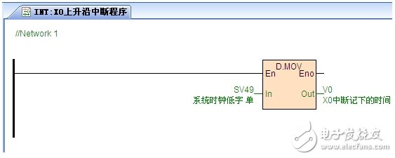
X0 rising edge interrupt program:
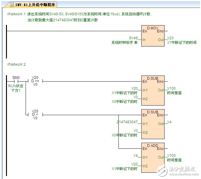
X1 rising edge interrupt program:
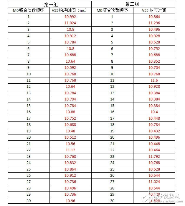
Measured with Haiwell H series mainframe, the time interval of relay pull-in is as follows (2 groups of 30 times):
Antenk extended its connector product range by SD card connectors. As already mentioned there are various applications, in the past driven by the computer industry, which are using memory cards as well in their end products, single sided pressure contact connectors can be designed and manufactured according to a customer specific requirement based on customer dedicated insulator- and contact dies. Such single sided pressure contact connectors are mainly used as board to board connection on the base of direct contact to the pads on the board.
Compact Flash Card Connector Overview
Store More Memories
Compact Flash storage cards are small, removable, mass-storage devices. They electrically comply with Compact Flash Association standards, the PC Card ATA standard, and run in True IDE mode. These 50-position cards typically hold between 32 MB and 2 GB of memory and are about the size of a matchbook. Antenk`s connectors include headers that can accept Type I (3.3mm thick) or Type II (5.0mm thick) storage cards, flush and raised mounting heights, and ejectors. Antenk Compact Flash card connectors also provide electrostatic discharge protection.Adapter for Compact Flash Card type I and II
Available with various ejectors
Different stand offs heights
Reverse type without stand-off height is not applicable to Compact Flash Card Type II
Compact Flash Card Connector Specification
Insulation Resistance: 1000MΩ at 500V DC
Withstanding Voltage: 500Vrms
Current Rating: 1A AC/DC max.
Contact Resistance: 40mΩ max. at 20mV max.
Operating Temp. Range: -55°C to +85°C
Reflow Solder Temp.: 220°C min. / 60 sec, 260°C peak
Mating Cycles: 10,000 times
Materials and Finish
Insulator: LCP, glass filled (UL94V-0)
Push Button: Glass reinforced PBT (UL94V-0)
SMT Metal: Brass, pure Sn
Pivot Shell: Stainless Steal
Contacts: Brass
Plating: Contacts - Gold (15µ[) over Nickel (40µ[), Solder Tails - pure Sn
Compact Flash Card Connector Product Features
Compact Flash Connectors
Robust surface-mountable designs
Proven PCMCIA contact technology
Accepts hardware for mechanical mounting
Top- and bottom-mounting styles
Right-angle and vertical orientations
Compact Flash Connectors Applications
Desktop and laptop computers
Digital cameras
Smart phones
Data recorders
Slot machines
Industrial and embedded computers
SD Card Connector,Tf Card Connector,Sd Card Connector,Natural Cf Card Connector,Compact Flash Card Connector,CF cards types I/II,CF Card connector MA type Adapter,CF Card connector MA type Ejector
ShenZhen Antenk Electronics Co,Ltd , https://www.antenkcon.com