First, H bridge drive circuit
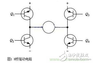
A typical DC motor control circuit is shown in Figure 1. The circuit takes its name from the "H-bridge driver circuit" because its shape resembles the letter H. The four triodes make up the four vertical legs of H, and the motor is the horizontal bar in H (Note: Figure 1 and the subsequent two figures are just schematics, not a complete circuit diagram, where the triode's drive circuit is not shown).
As shown, the H-bridge motor drive circuit includes four triodes and one motor. To operate the motor, a pair of transistors on the diagonal must be turned on. Depending on the conduction of the different pairs of transistors, current may flow through the motor from left to right or from right to left, thereby controlling the steering of the motor.
To operate the motor, a pair of transistors on the diagonal must be turned on. For example, as shown in Figure 2, when the Q1 tube and the Q4 tube are turned on, the current passes from the positive pole of the power supply through the Q1 from left to right through the motor, and then back to the negative pole of the power supply via Q4. As indicated by the current arrow in the figure, the current in the flow direction will drive the motor to rotate clockwise. When transistors Q1 and Q4 are turned on, current will flow from left to right through the motor, causing the drive motor to rotate in a particular direction (the arrow around the motor indicates a clockwise direction).
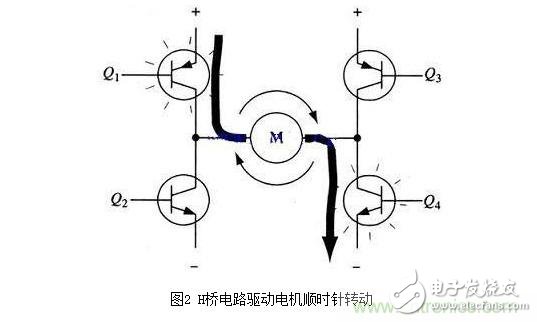
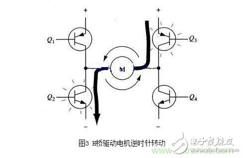
Figure 3 shows the other pair of transistors Q2 and Q3 conducting, current flowing from right to left through the motor. When transistors Q2 and Q3 are turned on, current will flow from right to left through the motor, causing the motor to rotate in the other direction (arrows around the motor are shown as counterclockwise).
Second, enable control and direction logic
When driving the motor, it is important to ensure that the two transistors on the same side of the H-bridge are not turned on at the same time. If the transistors Q1 and Q2 are turned on at the same time, the current will flow directly from the positive electrode through the two transistors to the negative electrode. At this point, there is no load other than the triode in the circuit, so the current on the circuit can reach a maximum (this current is only limited by the power supply performance), and even burn out the triode. For the above reasons, it is common to use a hardware circuit to conveniently control the switching of the triode in an actual driving circuit.
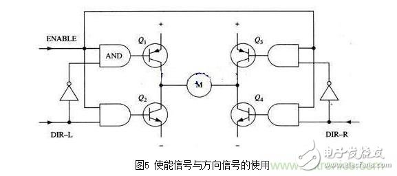
The improved circuit adds four AND gates and two NOT gates to the basic H-bridge circuit. The four "enable" turn-on signals are connected to the gate so that the switch of the entire circuit can be controlled with this signal. The two non-gates can ensure that only one transistor can be turned on at the same leg of the H-bridge at any time by providing a direction of input. (As with the previous diagram in this section, Figure 4 is not a complete circuit diagram. In particular, the direct connection to the gate and the triode does not work properly.)
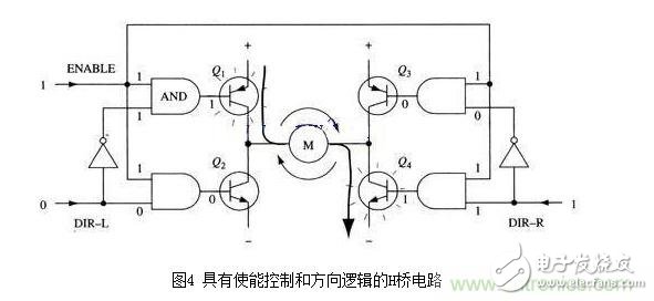
With the above method, the operation of the motor only needs to be controlled by three signals: two direction signals and one enable signal. If the DIR-L signal is 0, the DIR-R signal is 1, and the enable signal is 1, then the transistors Q1 and Q4 are turned on, and the current flows from left to right through the motor (as shown in Figure 5); if DIR-L The signal changes to 1, and the DIR-R signal becomes 0, then Q2 and Q3 will turn on and current will flow through the motor in the opposite direction.
In actual use, it is very troublesome to make H-bridges with discrete components. Fortunately, there are many packaged H-bridge integrated circuits on the market, which can be used with power, motor and control signals, at rated voltage and current. Internal use is very convenient and reliable. For example, commonly used L293D, L298N, TA7257P, SN754410 and so on.
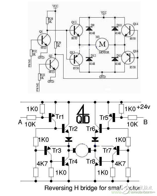
H-bridge drive circuit with two discrete components:
Aluminum substrate is a metal-based copper clad laminate with good heat dissipation function. Generally, a single-sided panel consists of three-layer structure, which are circuit layer (copper foil), insulating layer and metal base layer,and are usually used in products that require heat dissipation, such as solar energy,Led light etc.
Metal Core PCB,FR4 PCB Board,Double-sided Aluminum PCB,Single Sided Board,Aluminum Based Circuit Board
Huizhou Liandajin Electronic Co., Ltd , https://www.ldjpcb.com