This article first introduces the general knowledge of radio direction finding, explains the classification method and application of radio direction finding machine, emphasizes on the principle of direction finding principle, explains the characteristics of different direction finding systems and the main technical indicators; Suggest. For readers' reference.
General knowledge of radio direction finding
With the widespread use of radio frequency resources and the increasing popularity of radio communications, radio monitoring and radio direction finding are essential for the orderly and reliable use of limited spectrum resources and for ensuring the smooth flow of radio communications. Their status and role are also important. Will keep up with the times.
What is radio direction finding? Radio direction finding is based on the propagation characteristics of electromagnetic waves, using instruments to determine the direction of the arrival of radio waves. The special equipment for measuring the direction of radio waves is called a radio direction finder. In the measurement process, the direction finding systems can be divided into two categories according to the way the antenna system obtains information from the arriving arrival signals and the information processing methods: scalar direction finding systems and vector direction finding systems. The scalar direction finding system can only obtain and use the scalar information data related to the arriving wave signal; the vector direction finding system can obtain and use the vector information data of the arrival arrival wave signal. The scalar direction finding system can only obtain and use the amplitude or phase information of the electromagnetic wave separately, and the vector direction finding system can simultaneously obtain and use the amplitude and phase information of the electromagnetic wave.
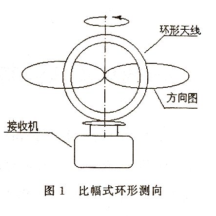
Scalar direction finding systems have a long history and are the most widely used. The simplest magnitude comparison scalar direction finding system is a rotating ring type direction finding machine as shown in Fig. (1). This system forms a figure of eight for vertical polarized waves. Most scalar direction-finding systems with amplitude-comparison type, their DF antennas and directional patterns are all in a symmetrical form, such as: Adcock direction finder and Watson-Watt (Watson) -Watt) direction-finding machines, and various round-antenna array direction-finders using a rotary angle meter; scalar direction-finding systems that are phase-comparable, like: Inteferometry direction-finding machines and Doppler (Doppler) Direction measuring machine. The short wave scalar direction finding system can be designed to measure only the azimuth angle, and can also be designed to measure the azimuth angle while measuring the elevation angle of the incoming wave.
The vector direction finding system has the ability to obtain and use vector information data from a wave signal. For example: spatial spectrum estimation direction finding machine. For data acquisition of vector systems, the front-end needs to use a multi-port antenna array and use at least two receivers with the same amplitude and phase at the same time, and the back-end is solved by the computer according to the corresponding mathematical model and algorithm. Based on the number of antenna units and receivers and the subsequent processing capabilities, the vector system can distinguish between two and even multiple wavefields and directions of arrival. The development of the vector direction finding system is still a matter of more than ten years. Its realization depends on the progress of digital technology, microelectronic technology and digital processing technology. It is not yet universal.
In the above explanation, we used the method of measuring the "direction of arrival" without using the "direction of the radiation source". There is a difference between the two. We focus here on the actual electromagnetic environment where the direction-finding machine is located. However, the ultimate goal of radio direction finding is to determine the “direction of the radiation source†and the “specific location of the radiation sourceâ€.
Radio direction finding has emerged from the beginning of the last century and has formed a systematic theory. This is radio direction finding. Radio direction finding is a method to study electromagnetic wave characteristics and propagation law, radio direction finding principle and implementation method, direction-finding error law, and reduce and overcome errors. In short, radio direction-finding is the science of studying radio direction finding theory, technology and application. Radio direction finding is a science closely related to radio engineering, radio electronics, geophysics, radio communication technology, computer technology, and digital technology.
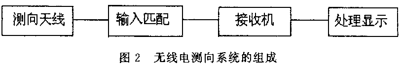
The composition of the radio direction finding system is shown in figure (2). Usually includes four parts of direction finding antenna, input matching unit, receiver and orientation information processing display. The direction-finding antenna is a detector, sensor and energy converter of the electromagnetic field energy. It receives the electromagnetic wave energy propagated in the air, and converts the information including amplitude, phase and arrival time into an alternating current signal and feeds it to the receiver. The matching unit implements the antenna-to-receiver matching transmission and necessary transformation; the role of the receiver is frequency selection, down-conversion, distortion-free amplification and signal demodulation; detection, comparison, calculation, processing, display (indicating) azimuth information, and The task of the fourth part.
The radio direction finding is based on the location of the direction finder and the meridian over the geographic north as the reference zero degree direction. The degree of orientation between two points is determined as follows: Suppose the two points A and B on the surface of the earth, point A is the location of the direction finding machine, and the reference direction and azimuth angle are shown in figure (3). Measuring the azimuth of point B with respect to point A is the number of degrees of rotation of the big circle connecting clockwise from the meridian (zero degree) over A point to A to B. Point B is unique with respect to the azimuth angle of point A
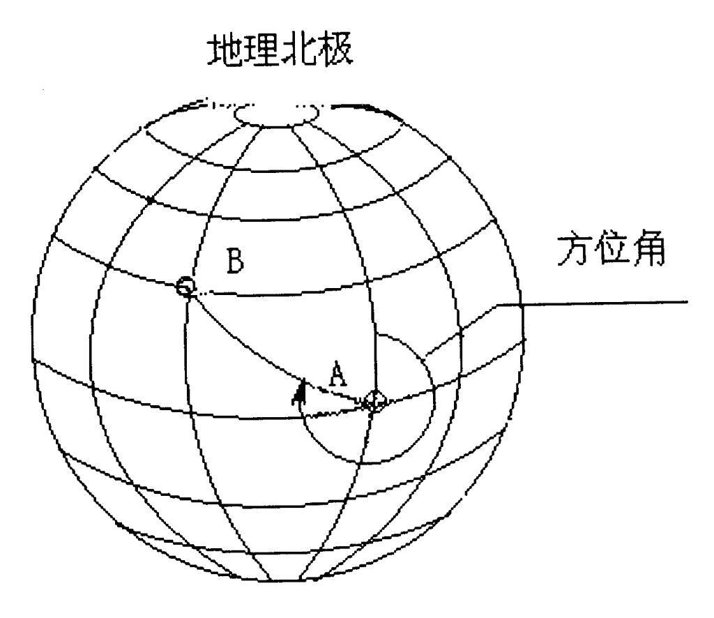
Figure 3 Reference direction and azimuth
The direction-finding reading displayed (indicated) by the direction-finding machine during direction finding is called orientation. Due to radio wave propagation and the error of the direction-finding instrument, the direction of orientation is usually not a very accurate single value during direction finding. The difference between orientation and azimuth is called direction-finding error. If the direction of orientation coincides with the azimuth angle in direction finding, the direction-finding error is zero. In fact, the causes of errors in the direction finding process are many, but basically it can be summarized as two major aspects: subjective error and objective error. There are many factors that influence and produce objective errors.
In direction finding, in order to obtain a more accurate orientation, there are usually four conditions that must be met: an excellent direction-finding site environment, a matching direction-finding system, a high-precision direction-finding machine, and an experienced operator. Excellent direction-finding site environment provides conditions for normal propagation of radio waves; correct selection of direction-finding system to meet different requirements in use; sophisticated direction-finding machine is the basis of equipment; in the process of direction finding, it is often necessary to deal with unexpected Situation, people's knowledge and experience are very valuable, and experienced operators have a very important role. This is the condition that four must have at the same time.
Direction finding equipment, communication systems and auxiliary equipment can form direction-finding stations (stations). The direction-finding station is an organization that specifically performs the direction-finding mission. It has the separation of fixed stations and mobile stations.
The direction of the radio wave is measured by radio direction finding, usually to determine the position of the radiation source. At this time, the direction of the direction finding station (station) network with different positions is often used, and the orientation of each direction finding station is used (line ) Converge. As shown in Figure 4. When conditions permit, it is also possible to use a mobile direction-finding station to time-sequentially cross-check at different locations.
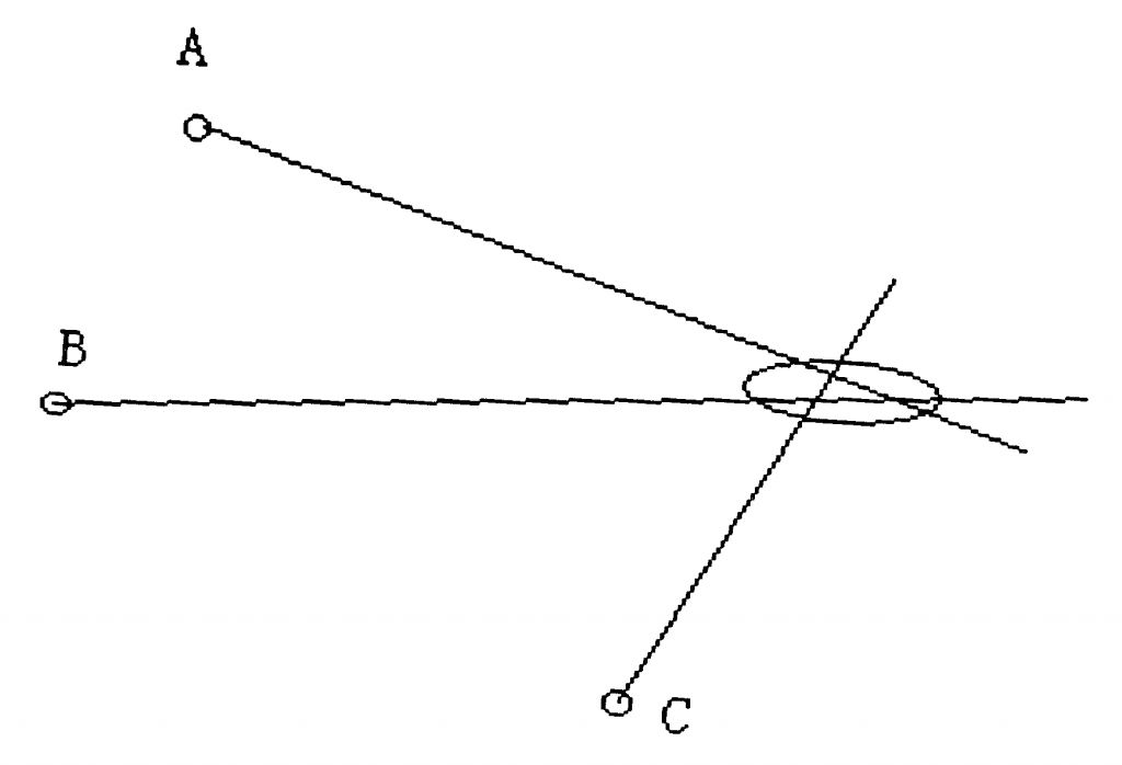
Fig. 4 Directional intersection of each direction-finding station
The short-wave single station positioning is to measure the elevation angle of the incoming wave while measuring the direction, calculate the distance by the elevation angle and the ionosphere height, and use the orientation degree and the distance to determine the platform position. Single station positioning is shown in Figure (5).
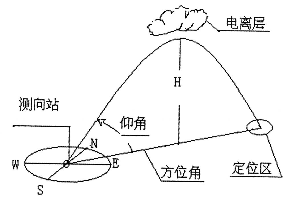
Figure 5 short wave single station (station) positioning
In actual operation, it is necessary to determine the specific location of the unknown radiation source, and it is often necessary to perform far and near step-by-step cross-testing to gradually achieve close to and determine the specific location of the radiation source.
Application of radio direction finding
The application of radio direction finding system is in three aspects: 1. Direction finding system for measuring the direction and position of unknown radiation source. The direction-finding station (station) can be fixed or mobile. For example, in the radio spectrum management, the direction and location of unknown interference sources. Second, determine the direction of known radiation sources, to determine its own location of the direction-finding system. The direction finder is usually mounted on a moving carrier. For example: Navigation equipment in navigation of ships and aircraft. Third, guide the direction-finding system with a radiation carrier to reach a predetermined target. The direction-finding station (station) can be fixed or mobile.
The application of radio direction finding includes civil and military applications. Radio frequency spectrum management, natural ecological research, aviation management, land search and navigation, internal security and sports, etc., belong to the former; communication and non-communication signal reconnaissance, strategic tactical electronic countermeasures and opposition, etc., in the application of electronic warfare, Belong to the latter.
Radio direction finding machine classification method
After nearly a hundred years of research, practice and development, radio direction finding machines have had a huge family. Based on the differences in focus, the direction finding machine has the following different classification methods (the cross is inevitable in the classification): 1. Classification according to the working frequency band: ultra-long wave, long wave, medium wave, short wave, ultra-short wave and microwave direction finding machine 2. According to the working methods, there are: fixed direction-finding machine and mobile direction-finding machine. The mobile direction-finding machine can be further divided into vehicle-mounted, ship-borne, airborne (aircraft) direction-finding machines and hand-held and wear-type direction-finding machines because of different means of delivery; 3. Classification according to the distance of the direction-finding machine (mainly referred to as Shortwave) includes: Near-range direction finding machine, middle-range direction finding machine, and far (range) distance direction finding machine; 4. Classification according to size of direction finding antenna spacing (base, aperture): large-basic direction finding machine, middle Basic direction finding machine, small base direction finding machine; 5. According to whether the direction-finding antenna has amplifiers: active antenna direction-finding machine, passive antenna direction-finding machine; 6. direction-finding antenna type used according to the direction-finding machine The categories are: ring (frame) antenna direction finding machine, cross ring (frame) antenna direction finding machine, spacing double ring (frame) antenna direction finding machine, monopole (loading) antenna direction finding machine, symmetrical element (vertical , Horizontal) Antenna direction finding machine, Logarithmic antenna direction finding machine, Traveling wave loop antenna direction finding machine, Magnetic antenna direction finding machine, Microwave lens antenna direction finding machine, etc.; 7. Classification according to direction finding machine orientation reading mode There are: audible direction finding machine, vision direction finding machine, digital direction finding machine; 8. using receiver according to direction finding machine Road classification: single, dual-channel finders, multichannel finder. Like the above classification methods, there may be some, which will not be repeated here. Directional principle and direction finding system overview.
In the direction finding machine family, according to different direction finding principles, existing direction finding machines can be classified into different direction finding systems, systems and styles. The following will introduce their working principles and characteristics.
First, amplitude comparison type direction finding system
The working principle of the amplitude comparison type direction finding system is: according to the direction characteristics of the direction-finding antenna array or the direction-finding antenna, the direction of the incoming wave is determined according to the amplitude of the received signal in different directions.
For example, a four-element U-shaped antenna array and a small-basic measurement (Adec) machine set at intervals, as shown in Fig. (6). Its expression formula is shown in formula (1). Uns=kU13SinθCosεUew=kU24CosθCosεUnsθ=arctg—— (1) Uew
In the above formula: Uns, Uew are north-south, east-west antenna induced voltage, θ is incoming wave azimuth, ε is incoming wave elevation angle, k is phase constant, 2bπk = — λ where: b is the antenna Spacing, λ is the operating wavelength.
For the incoming wave with different directions of 360 degrees (θ), the amplitude of the north-south antenna induced receiving signal follows the sine law of Sinθ, and the amplitude of the sensing signal of the east and west antenna follows the law of cosine Cosθ. With two sets of signal amplitudes, the direction finding direction The two solutions or display their arc tangent, you can get the incoming wave direction. This is just an example of a typical direction finding machine in the amplitude comparison direction finding system.
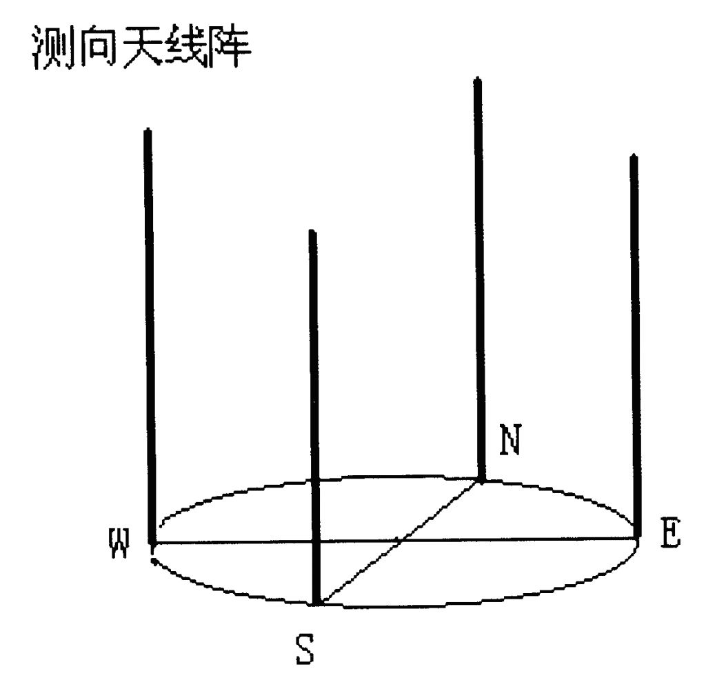
Figure 6 Four-cell Adkoc antenna array
The principle of amplitude comparison type direction finding system is widely used, and the direction of its direction finding machine is also not the same. For example: loop antenna direction finding machine, spaced double loop antenna direction finding machine, rotating logarithmic antenna direction finding machine, etc., belonging to direct rotation direction finding antenna and directional pattern; cross loop antenna direction finding machine, U-shaped antenna direction finding machine, type H Antenna direction finding machines, etc., belong to indirect rotating direction finding antenna patterns. Indirect rotation of the DF antenna pattern is achieved through manual or electrical rotation of the angle meter. Hand-held or wear-type direction-finding machines are usually also amplitude comparison type direction-finding systems. This is not repeated.
The characteristics of the amplitude comparison type direction finding system: The direction finding principle is intuitive and intuitive. In general, the system is relatively simple, small in size, light in weight and cheap in price. The small-foundation direction finding system (Adkock) has spacing error and polarization error, and the ability to resist wavefront distortion is limited. Frequency coverage, direction-finding sensitivity, accuracy, direction-finding, anti-multipath capability, and anti-jamming capability are important indicators that need to be analyzed based on specific conditions.
Second, Watson-Watt direction system
The Watson-Watt direction finding system works: The Watson-Watt direction finding machine is actually a direction-finding system with amplitude comparison. However, it does not use direct or indirect rotation of the antenna pattern at the time of direction finding. Solve or calculate the arc tangent using a calculation. Given its special position in the direction-finding machine family and it is still widely used, it is described separately here. The basic formula is the same as formula (1). Orthogonal (Sinθ, Cosθ) direction-finding antenna signals are frequency-converted and amplified by two receivers with the same amplitude and phase characteristics. Finally, the inverse tangent value is solved or displayed, and the direction of the incoming wave is solved or displayed. Among the Watson Watt direction finders are: multi-channel Watson-Watt direction finders, single-channel Watson-Watt direction finders. The multi-channel mentioned here usually refers to three channels, and the role of another channel is to connect with the omnidirectional antenna to solve the problem of "180 degree uncertainty" and "duty reception". The multi-channel Watson-Watt direction finding block diagram is shown in Figure (7).
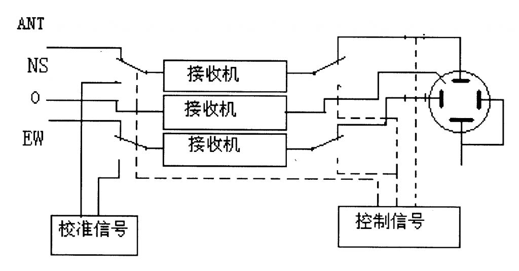
Figure 7 Multi-channel Watson-Watt Block Diagram
The single-channel Watson-Watt direction finder is a quadrature directional antenna signal, modulated by two low-frequency signals, and then frequency-converted and amplified by a single-channel receiver to demodulate the direction information signal, and then solve or display. The inverse tangent value gives the incoming wave direction. The schematic block diagram of the single channel Watson-Watt direction finder is shown in (8).
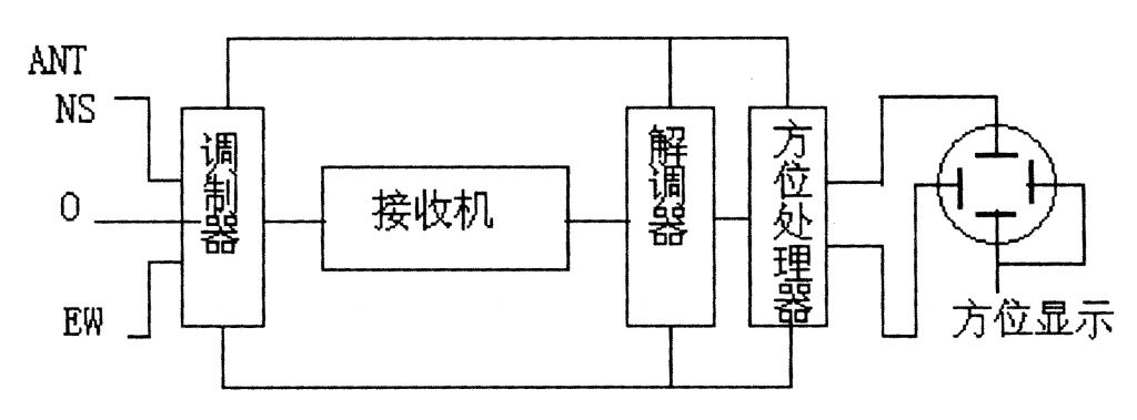
Figure 8 Single Channel Watson-Watt Block Diagram
The characteristics of the Watson-Watt direction finding system: The multi-channel Watson-Watt direction finder has a high directionality, high speed, accurate directionality in a good field, and the CRT display mode can also identify co-channel interference. This system-oriented antenna is a small base, and the DF sensitivity and anti-wavefront distortion are limited. The multi-channel system system is complicated. The dual-channel receiver achieves the same amplitude and phase with certain technical difficulties. The single-channel system also belongs to a small foundation, the system is simple, the volume is small, and the weight is light, but the direction-finding speed is limited. 
Third, the interferometer direction finding system
The direction finding principle of the interferometer direction finding system is that according to the radio wave traveling, when the waves from different directions arrive at the direction finding antenna array, the phase received by each direction finding antenna element in space is different, and the phase difference between them is also different. Differently, the arrival direction can be determined by measuring the phase and phase difference of incoming waves. The basic formula is as shown in formula (2): Φ13=Φ1-Φ3=k*SinθCosεΦ24=Φ2-Φ4=k*SinθCosεΦ13θ=arctg———(2)Φ24 In the above formulae: Φ13, Φ24 are North-South and East respectively. - The phase difference of incoming waves between the west antenna, k is the phase shift constant, and θ is the desired incoming wave direction angle.
In the interferometer direction-finding mode, the phase of the induced voltage of the DF antenna is directly measured, and then the phase difference is solved. The formula of (2) can be seen to be very similar to the formula of the amplitude comparison type direction finding.
In order to be able to determine the direction of electromagnetic wave arrivals in a single value, the interferometer direction finding operation requires that at least three separate DF antennas be installed in space. The interferometer measures the phase by a single value within ±180 degrees. When the antenna spacing is small, the resolving power of the phase difference is limited. If the antenna spacing is more than 0.5 wavelengths, phase blurring may occur. The usual solution to this contradiction is to insert one or more additional elements along each of the main baselines. These additional elements provide additional phase measurement data from which the ambiguity in the primary baseline phase measurement is resolved. This baseline-changing technique has been widely adopted for contemporary interferometer direction finding machines. The principle of the direction finding principle of the interferometer direction finding machine is shown in figure (9).
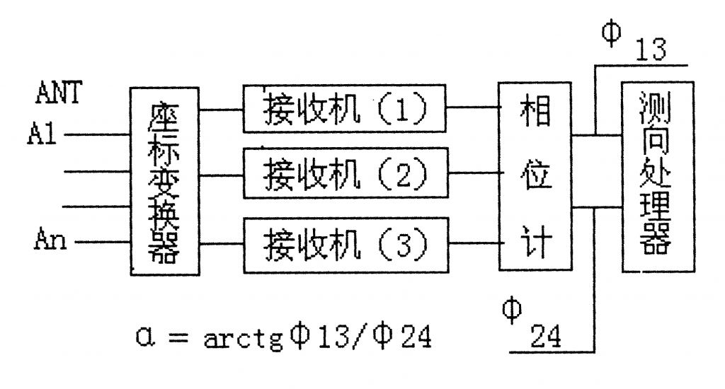
Figure (9) Interferometer Direction Finding Block Diagram
The correlation interferometer direction-finding is a kind of interferometer direction-finding. Its principle of direction-finding is: in the range of working frequency of the direction-finding antenna array and in the direction of 360 degrees, each point is set according to a certain rule, and at the same time in the frequency interval and azimuth. At the interval, a sample group is established. In the direction finding, the measured data is correlated with the sample group and interpolated to obtain the direction of the incoming wave signal. Reprint please specify from the instrument bureau
The characteristics of interferometer direction finding system: using variable baseline technology, it can use medium and large basic antenna arrays, multi-channel receivers, computers, and FFT technology, making the system has high sensitivity in direction finding, high direction-finding accuracy, and direction-finding speed. Fast, measurable elevation angle, a certain degree of anti-wavefront distortion. The system polarization error is insensitive. Interferometer direction measurement is a relatively good direction-finding system in the modern era. Due to the complexity of the development technology and the difficulty, the cost is relatively high. The interferometer direction-finding is insensitive to the amplitude of the received signal. The distribution of the DF antenna in space and the spacing of the antenna are more flexible than the amplitude comparison type, but it must follow certain rules. For example, it may be a triangle, a pentagon, an L-shape, or the like.
Fourth, Doppler direction finding system
Doppler direction finding system's principle of direction finding: According to the propagation of the electric wave, when it encounters the direction-finding antenna that moves relative to it, the received electric wave signal produces a Doppler effect, and the frequency shift generated by the Doppler effect is measured. You can determine the direction of the incoming wave.
In order to obtain the frequency shift generated by the Doppler effect, relative motion between the direction finding antenna and the radio wave to be measured must be made. Usually, the direction finding antenna is implemented in the receiving field with a sufficiently high speed movement. When the antenna is fully moving in the direction of the incoming wave, the Doppler effect has the largest amount of frequency shift (rise). The basic formula for Doppler direction finding is shown in formula (3).
When the direction-finding antenna makes a circular motion, the phase of the incoming wave signal will be sinusoidally modulated. Suppose that the center of antenna field 0 is the phase reference point, the phase of the signal is Φ, and the instantaneous phase of the antenna receiving signal is Φ(t), so there is: Φt=ωt+Φ+kcCos(Ωt-θ)
Where: ω is the signal angular frequency, Ω is the antenna rotation angle frequency, θ is the direction of the incoming wave direction, phase constant kc = 2πr/λ, where r is the antenna spacing and λ is the signal wavelength.
The expression Ut received by the DF antenna is: Ut = Acos [ωt + Φ + kcCos (Ωt - θ)]
The Doppler effect causes the signal received by the DF antenna to be phase modulated and the Doppler phase shift is ΦD, so there is: ΦD = kcCos (Ωt - θ)
The corresponding Doppler shift is: f=dΦD/dt=-kcSin(Ωt-θ) (3)
The Doppler frequency shift f can be obtained from the signal received by the rotating direction-finding antenna after the frequency conversion, amplification, and frequency discrimination of the receiver. The direction of the incoming wave θ can be obtained by comparing the Doppler shift f with the 0-point reference frequency.
Doppler direction finding usually does not directly rotate the direction finding antenna, because it is difficult to achieve in engineering. It is based on the multi-guy antenna mounted on the circumference of the concentric circle. The electronic switch is quickly connected to each antenna in sequence, which is equivalent to the rotation measurement. To the antenna. People call this direction-finding machine a quasi-Doppler direction finder. The quasi-Doppler direction finding block diagram is shown in figure (10).
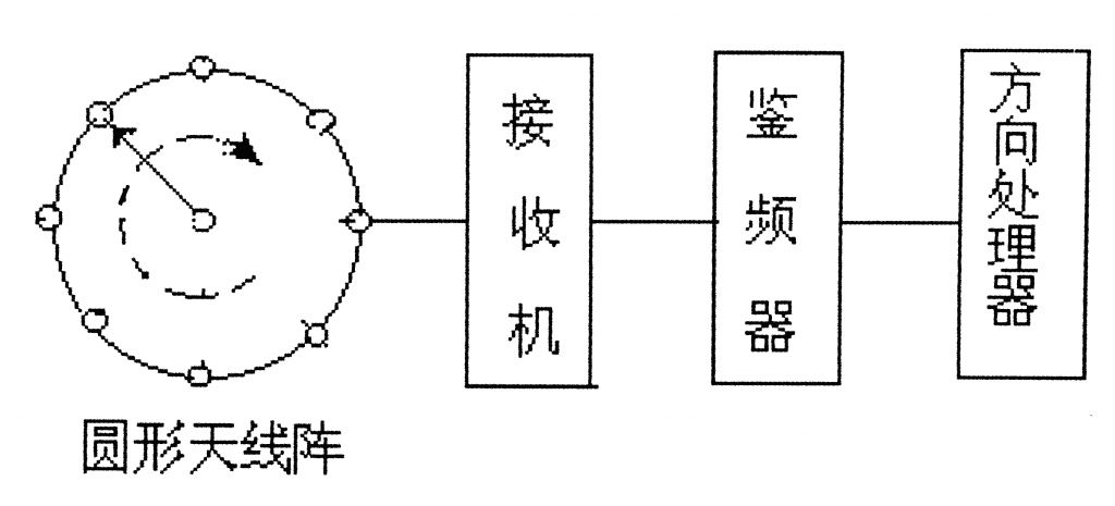
Figure 10 quasi-Doppler direction measurement block diagram
Usually people want to get a large Doppler frequency shift, increasing the antenna aperture and switching speed is the basic approach. The Doppler direction-finding machine's DF antenna aperture can use large and medium-sized bases; the switching rotation frequency is several hundred Hertz, and the Doppler frequency can be called f can reach several hundred Hz, but the increase of the switch rotation frequency can result in the generation of The bandwidth of the sideband increases, thus limiting the speed.
The characteristics of the Doppler direction finding system: Medium and large basic antenna arrays can be used, with high sensitivity in direction finding, high accuracy, no spacing error, small polarization error, measurable elevation angle, and certain anti-wavefront distortion capability. The defect of the Doppler direction finding system is poor anti-interference performance. For example, when co-channel interference and FM modulation interference are encountered, DF errors will occur. The system is still under development. Improvement will complicate the system and the cost will increase.
V. Ulan Weber direction finding system
Ulan Weber direction finding principle of the direction finding system: using a large-basis direction-finding antenna array, setting up a plurality of direction-finding antennas on the circumference, the incoming wave signal passing through a rotatable angle meter, a phase-shifting circuit, and a difference circuit, forming a joint The difference pattern is then fed to the receiver. Rotate the angle meter and rotate the misalignment pattern to find the wave direction.
Taking 40 feed antenna array elements as an example, the angle meter can be coupled with 12 antenna elements instantaneously, and then phase-aligned with a phase shift compensation circuit to form a rotatable equivalent linear antenna array. The 12 antennas are divided into two groups. , Each group pays 6 and the two groups are added and subtracted through a common circuit to form a combination and difference pattern. In the direction of direction, the direction of the incoming wave is measured by the combination and difference patterns. In the direction of the incoming wave, since the two sets of antennas are all on the isochronal plane of the incoming wave, the signals of the two sets of antennas are equal in magnitude. When the difference pattern is the difference, the output is subtracted to “zeroâ€. When the patterns are combined, it is a set of antennas. Two times the signal output.
Since Ulan Weber's direction is a phase comparison, it is often classified as a phase-flight machine. However, from the point of view of the user, the signal amplitude is eventually used, so it is reasonable to say that it is an amplitude comparison type direction finding machine. The Ulanweber direction finding block diagram is shown in figure (11).
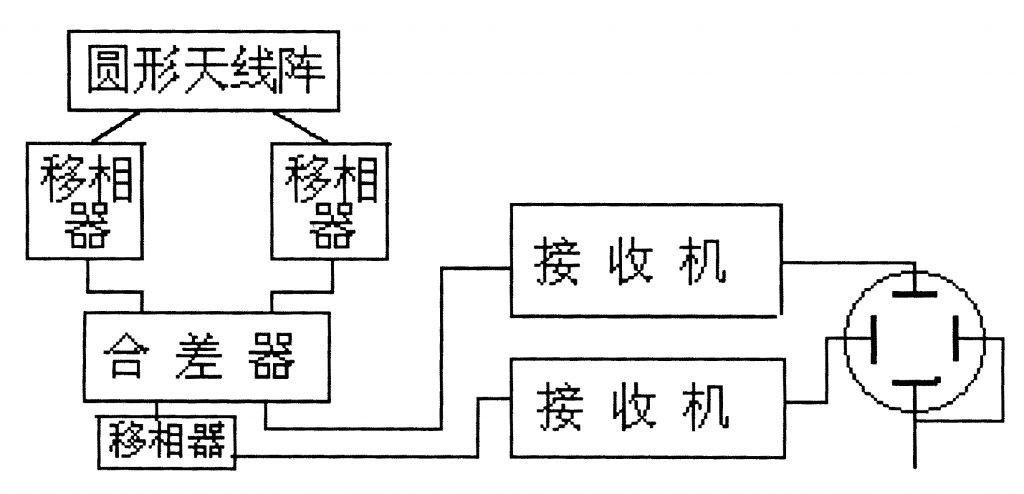
Figure 11 Ulan Weber direction finding block diagram
The short wave Ulan Weber direction finding system is a typical large base, and the diameter of the direction finding antenna array is 1 to 5 times the minimum operating wavelength. Antenna array diameter size, according to different low-end operating frequency, reach hundreds or even thousands of kilometers. The direction-finding antenna unit may be a wide-band upright antenna or a log-periodic antenna. In order to improve the antenna reception efficiency, a reflection network is usually used inside the antenna array. When an antenna array is difficult to cover all the short-wave frequency bands, a double-layer array of inner high frequency and low frequency is generally used.
Ulan Weber's direction finding system features: Due to its large base antenna array, it has high sensitivity in direction finding, high direction finding accuracy, high DF resolution, anti-wavefront distortion and good anti-jamming performance, and can provide comprehensive monitoring and utilization. Due to the Ulanweber direction finding machine requires dozens of antennas and feeders with the same electrical characteristics, plus the design of the angle meter, high process requirements, and the need for a large and flat open antenna installation site, this undoubtedly increases the difficulty of the cost and construction of the project. . The problem is that the cost is high and the direction of the survey site is high.
Sixth, arrival time difference measurement direction system
Time-of-arrival measurement The direction-finding principle of the direction-finding system: according to the time difference between the radio waves and the direction-finding antenna arrays, the direction of arrival of the radio waves is determined by measuring the arrival time of the radio waves on the direction-finding antenna array. It is similar to phase contrast, but the parameters measured here are time differences rather than phase differences. The direction finding system requires that the measured signal has a certain modulation method.
Arrival time difference The principle of direction finding principle is shown in formula (4). Suppose that the distance between the DF antenna units A and B erected vertically is 2b, the angle between the direction of the incoming wave and the line perpendicular to the AB line is θ, the elevation angle of the incoming wave is β, and the propagation speed of the radio waves is v, then the antenna B is more than the antenna A The delay time of the sensing signal is Ï„, 2b then: Ï„ = (-) SinθCosβv then the direction of the incoming wave θ can be found as: vτθ = arcSin[(———) Cosβ] (4) 2b In the above equation, Ï„ is The actual measurement time difference. The shortwave incoming wave elevation angle β needs to be estimated, and the ultrashort wave incoming wave elevation angle β is “zeroâ€, ie, Cosβ=1.
The direction finding principle block diagram is shown in (12).
In actual use, in order to cover the 360-degree direction, it is necessary to erect at least three separate direction-finding antennas. The distance between the DF antennas has long and short baselines, and the long-baseline DF accuracy is significantly better than the short baseline. Arrival time difference direction finding system is based on time standard and accurate measurement of time. With the current technical level, the measurement of time interval can reach 1 ns accuracy. When the distance is 10 meters, the accuracy of direction finding can reach 1 degree. .
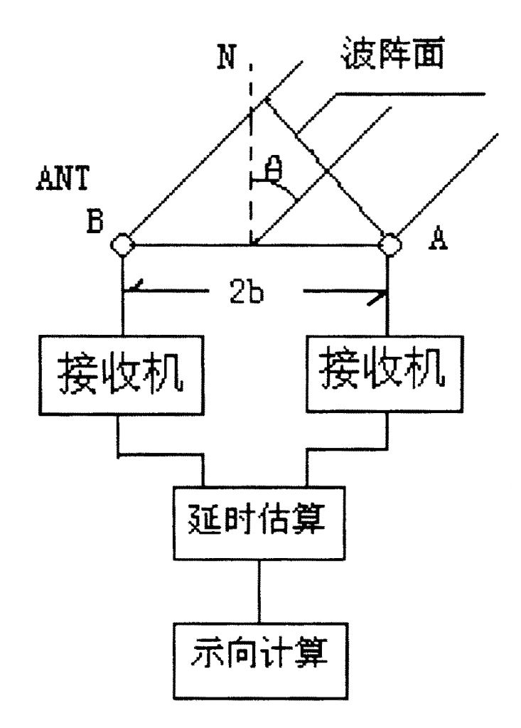
Fig.12 Functional block diagram of arrival time difference
Arrival time difference The characteristics of the direction-finding system are: high accuracy in direction finding, high sensitivity, fast direction-finding speed, insensitive polarization error, no space error, and low site-oriented site environmental requirements. But the anti-jamming performance is not good, the carrier must have a certain modulation, the current application is not yet popular.
Seventh, spatial spectrum estimation direction finding system
Spatial Spectrum Estimation Direction finding principle of direction finding system: In a multi-element antenna array with known coordinates, the wave parameters of the measurement unit or the multivariate electric wave field are converted and amplified by a multi-channel receiver to obtain a vector signal, and its sampling is quantized as The digital signal array is sent to the spatial spectrum estimator, and the parameters such as the arrival direction, elevation angle and polarization of each radio wave are determined by using the determined algorithm.
The spatial spectrum estimation direction finding principle block diagram is shown in figure (13).
Taking a quadrilateral antenna array as an example, the basic formula of the spatial spectrum estimation direction finding is shown in formula (5). The spatial spectrum estimation direction finding is to compare the received signal of each antenna with the signal of each other antenna. This is the correlation matrix method, that is, the covariance matrix method, which completely reflects the actual situation of the spatial electromagnetic field. Specifically, the covariance matrix is ​​constructed as follows:
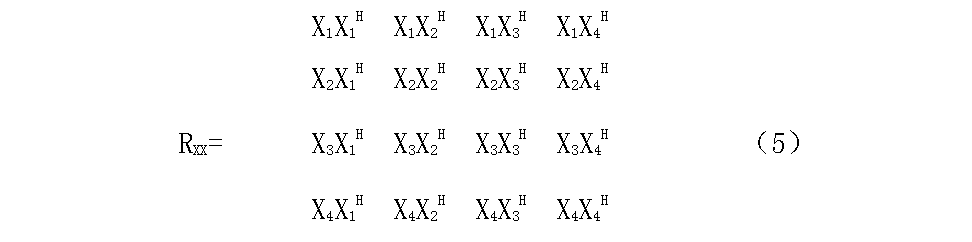
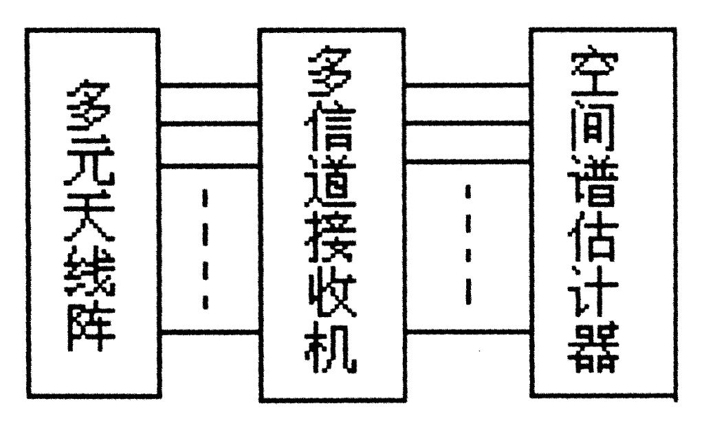
Fig. 13 Block diagram of spatial spectrum estimation direction finding
In the above formula: Xn is the output of antenna n, and H is the conjugate transpose symbol. The spatial spectrum estimation quadratic antenna array is shown in (14).
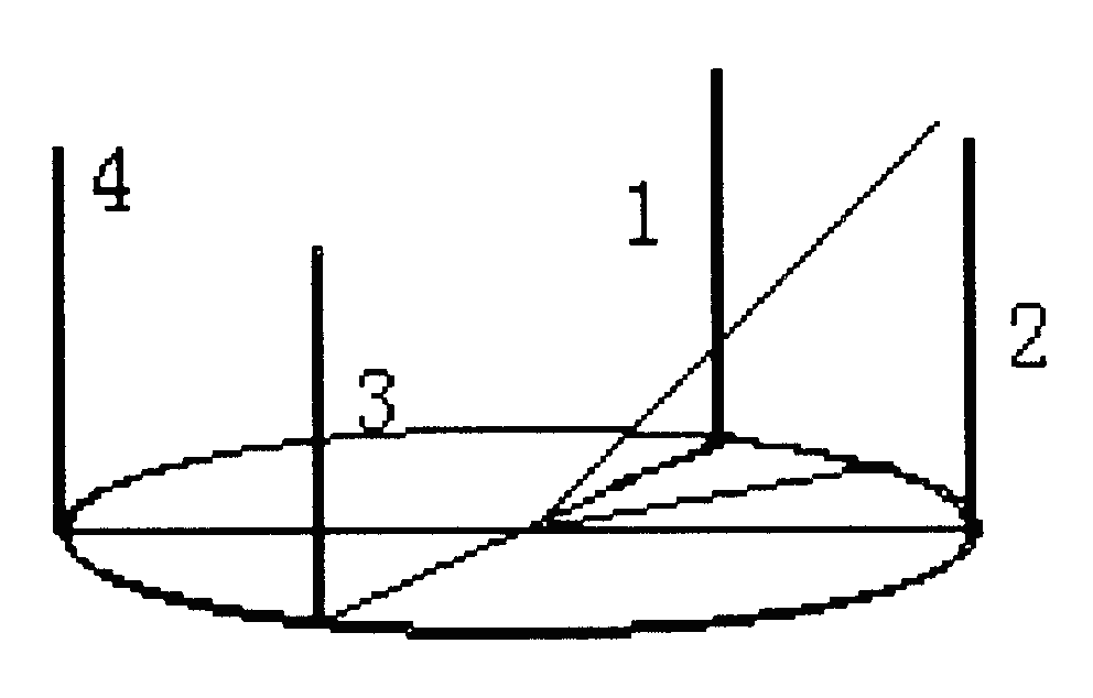
Fig. 14 Schematic diagram of the spatial spectrum estimation quad matrix
From equation (5), we can see that the covariance matrix of the quaternary matrix has 16 elements and the spatial spectrum estimates the direction finding. It fully utilizes all the information received from the space electromagnetic field by each array element of the DF antenna array, and the traditional direction finding method Only a small part of the information (phase or amplitude) is used, so traditional direction finding methods cannot function in multi-wave environments. Spatial spectrum estimation direction finding, based on the latest array processing theory, algorithms and techniques, has super-resolution direction finding ability. The so-called super-resolved direction finding refers to two or more radio waves within the same beam, which are simultaneously within the natural beam width of the antenna array, and can simultaneously measure the direction. This cannot be achieved in traditional direction finding methods. The formation of covariance matrix is ​​the basic starting point of spatial spectrum estimation, but the processing of covariance matrix is ​​not the same in different algorithms. The typical one is the multi-signal classification algorithm (MUSIC).
The characteristics of spatial spectrum estimation and direction finding system: spatial spectrum estimation and direction finding technology can realize simultaneous detection of several coherent waves; it can realize multiple signals in the same channel and exist simultaneously and measure direction; it can realize super-resolution direction finding. The spatial spectrum estimation direction finding, which requires only a few signal samples, can accurately measure the direction, so it is suitable for the direction-finding of frequency-hopping signals; the spatial spectrum estimation direction-finding can achieve high direction-finding sensitivity and high direction-finding accuracy. The DF accuracy is much higher than that of the traditional DF system. Even if the SNR drops to 0 dB, it can still work satisfactorily (while traditional DF system, SNR usually needs 20 db); The antenna array element directional characteristics selection and array element position selection flexibility can be achieved. The above advantages of spatial spectrum estimation and direction finding are the difficult problems that traditional direction finding methods have existed for a long time.
The spatial spectrum estimation is still in the experimental stage. In this system, it is required to have a wideband direction-finding antenna, which requires consistency between the individual antenna array elements and the multi-channel receiver. In addition, a simple and high-precision calculation method and a high-performance arithmetic processor are also required in order to solve practical problems.
Comparison of direction finding systems
The merits and demerits of the direction finding system are usually people's common concerns, but the radio direction finding system is also like all things, and each has its own duality. As far as users are concerned, each user's work environment, work methods, work requirements, and work targets are not the same. Therefore, in general terms, they may be separated from reality. When users choose the direction-finding system and the direction-finder equipment, it is important to thoroughly understand and carefully analyze their own work requirements. The strengths and weaknesses of the direction finding systems and equipment should be chosen by the users themselves on the premise of satisfying the work requirements. It should be said that each direction-finding system has its own characteristics. From the user's point of view, it can meet the needs of the work and the price is appropriate. This is the good system. Here, we focus on discussing from which aspects the direction-finding system and direction-finding equipment are evaluated, and put forward the following technical indicators for readers' reference.
First, the frequency coverage. This indicator regulates the performance indicators specified by the direction-finding machine and the frequency range of normal operation. It is the basic requirement for selecting the direction-finding system and direction-finding equipment.
Second, the direction of sensitivity. It characterizes the direction finding system and direction finding equipment's ability to find small (weak) signals. The direction-finding sensitivity mainly depends on the direction-finding antenna element form, the aperture (basis) and working mode of the antenna array. It is measured as the electric field strength and the unit is microvolts/meter (μv/m).
Third, the accuracy of direction measurement. It characterizes the accuracy of the direction finding system and the direction-finding equipment in direction finding, that is, the magnitude of the error in direction finding. The accuracy of direction finding usually includes the accuracy of instrumentation equipment, the accuracy of the direction measurement of standard equipment, and the accuracy of the precision of practical direction measurement. The physical meaning and test conditions of the three are fundamentally different. The user needs special attention and cannot mix dishes.
Fourth, anti-interference ability. It characterizes the direction finding capability and direction finding accuracy of the direction finding system and the direction-finding equipment when it encounters interference signals, including co-channel interference, inter-channel interference, out-of-band interference, multi-wavelength (wavefront distortion), etc. The direction finding ability when interference is present.
Fifth, measuring aging. It characterizes the time overhead of the direction finding system and direction finding equipment, as well as the ability to find short-signals in the air. This includes the time required for channel establishment, direction information sampling, data operation and processing (including integration), and orientation display of the direction finding system. Each time period can be expressed separately. However, in general, only comprehensive aging is often considered.
6. Polarization error. Polarization error is a kind of direction-finding error. It characterizes the direction-finding system and direction-finding equipment and works on the direction-finding ability under abnormally polarized wave conditions. Sometimes called polarization sensitivity, it is not sensitive. In the short wave band, the polarization error was tested with a standard oblique polarization.
Seven, elevation angle measurement. Shows whether the direction-finding system and equipment can measure the arrival angle of arrival. Short-wave direction finding, some direction-finding systems can measure the arrival angle of arrivals, and then achieve single-station positioning.
Eight, measuring distance. In short wave direction finding, there are usually remote direction finding, middle distance direction finding and close distance direction finding. Different direction finding distances have different requirements for equipment.
Nine, direction finding antenna base (aperture). Indicates the size of the direction-finding antenna array relative to the operating wavelength. The direction-finding antenna base (aperture) is divided into large, medium and small bases. The DF antenna base (aperture) directly affects DF performance.
Tenth, direction finding system and measurement parameters. Shows the direction-finding principle on which the direction-finding is based and the parameters of the measured wave. For example, when measuring the direction, the parameters such as amplitude, phase, time difference, etc. may be combined, which is related to the direction finding system.
Eleven, system mobility. Indicates the system's mobility. There are usually fixed, mobile and portable points. The movement is divided into vehicles, boats and airborne vehicles.
Twelve, system complexity and cost. It shows the complexity of the system of direction finding system and direction finding equipment and the technical difficulty in the development. It is consistent with the level of cost.
Conclusion:
With the continuous advancement of science and technology, radio monitoring and radio direction finding technology are also continuously improving, especially in recent years, with the rapid development of radio communications and network communications and the ever-changing changes in computer technology and microelectronics technology, radio monitoring technology will surely be promoted. The rapid development of direction-finding and direction-finding technologies has led to advancements in automation, intelligence, networking, and miniaturization; previously only theoretical things have become reality; highly digitized, integrated, and digital processing technology applications are improving radios. The performance of monitoring and radio direction finding equipment; the development and use of new technologies, new devices, and new processes are changing the face of traditional equipment; at the same time, new theories will continue to emerge, and the radio direction finding system will continue to be innovative. There is no end to all this change.
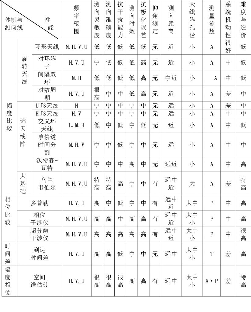
Appendix: Comparison of performance of various direction-finding methods
Interactive Board,Interactive Flat Panel,Interactive Whiteboard Classroom,Interactive Whiteboard Education
Interactive Board,Interactive Flat Panel,Interactive Whiteboard Classroom,Interactive Whiteboard Education
Jumei Video(Shenzhen)Co.,Ltd , https://www.jmsxdisplay.com