This article is mainly about the relevant introduction of dm9000ae, and focuses on the detailed description of the Ethernet interface design of the s3c2440 embedded system based on dm9000ae.
dm9000aeDM9000AE is an electronic product, store and forward.
Main features:
* Integrated 10/100M transceiver.
* Support MII/RMII interface.
* Support half-duplex back pressure flow control mode.
* IEEE802.3 full-duplex flow control mode.
* Support remote wake-up and connection status changes.
* Integrated 4K double word SRAM.
* Support memory and forwarding and EEPROM chip ID.
* Support 4 GPIO pins.
* Optional EEPROM settings.
* Low power consumption mode.
* I/O pins are compatible with 3.3V--5V.
* 48-pin cmos process LQFP package.
Application: interface conversion, set-top box, IP phone, monitoring processing, etc.
Product advantages:
Compared with similar products, it has the following unique advantages:
* LOCAL BUS chip, the basic characteristic of DM9000AE is 48pin, 10/100MLOCAL-BUS interface; working mode 8/16bit
* 2.5/3.5V low power consumption; DM9000AE is the world's smallest single chip, small size, easy to wire and plate
* Passed HP certification AUTO-Midx (supports direct interconnection and automatic flip) TCP/Ip acceleration (IPV4 check sum offioad)
Reduce the burden on the CPU, improve the performance of the whole machine, 20nsl/o read and write time
Ethernet interface design of s3c2440 embedded system based on dm9000aeWith the development of microelectronics technology and computer technology, embedded technology has achieved broad development and has become the development direction of modern industrial control, communication and consumer products. The excellent performance of Ethernet in real-time operation, reliable transmission, standard uniformity, and its advantages such as easy installation, simple maintenance, and no limitation of communication distance have been widely concerned by many researchers in the field of monitoring and control at home and abroad. Significant advantages are revealed in the application. This paper proposes a design scheme of Ethernet interface based on DM9000AE network interface chip and 32-bit Samsung ARM9 processor S3C2440 embedded system, and develops and transplants network drivers on Windows CE operating system to realize network access.
2. Working principle of DM9000AE
2.1 Main features and overall structure of DM9000
DM9000AE is a 10/100M fast Ethernet control chip developed by DEVICOM (Taiwan Lianjie International). DM9000AE realizes the functions of the Ethernet media media access layer (MAC) and physical layer (PHY), including MAC data frame assembly/disassembly and sending and receiving, address recognition, CRC encoding/checking, MLT-3 encoder, and receiving noise suppression , Output pulse shaping, timeout retransmission, link integrity test, signal polarity detection and correction, etc. The internal logic structure of DM9000AE is shown in Figure 1.
DM9000AE has the following main performance: ①48-pin LQFP package, small pins and small size; ②Support 8/16-bit data bus; ③Applicable to 10Base-T and 100Base-T, 10/100M self-adaptation, adapt to different network speeds Requirements: ④Built-in 16KB of SRAM, used for receiving and sending buffers, reducing the speed requirements of the main processor; ⑤Supporting IP/TCP/UDP acceleration, reducing the burden on the CPU and increasing network speed; ⑥Supporting Back pressure half-duplex flow control, Compatible with IEEE802.3u, support IEEE802.3x full-duplex flow control; ⑦20ns response time, 2.5V/3.3V low power consumption.
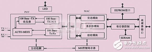
Figure 1 DM9000AE internal logic structure
2.2 Working principle
DM9000AE can be connected with the microprocessor in 8-bit or 16-bit bus mode, and can operate in simplex or full-duplex mode as required. When the system is powered on, the processor configures the DM9000AE internal network control register (NCR), interrupt register (ISR), etc. through the bus to complete the initialization of the DM9000AE. Then DM9000A enters the waiting state for data sending and receiving.
When the processor wants to send a data frame to the Ethernet, it first packs the data into a UDP or IP data packet, and sends it byte by byte to the data sending buffer of the DM9000A through the 8-bit or 16-bit bus, and then fills the data length and other information into the In the corresponding register of DM9000AE, then send the enable command, DM9000AE will MAC framing the buffered data and data frame information, and send it out.
When DM9000AE receives the Ethernet data from the external network, it first checks the validity of the data frame. If the frame header flag is wrong or there is a CRC check error, the frame data will be discarded, otherwise the data frame will be cached in the internal RAM , And notify the processor through the interrupt flag bit. After the processor receives the interrupt, it processes the data of the DM9000AE receiving RAM.
DM9000AE automatically detects the network connection and sets the internal data transmission and reception rate to 10Mb/s or 100 Mb/s according to the network speed. At the same time, DM9000AE can also change the direction of the data receiving and sending pins according to the connection mode of the RJ45 interface. Therefore, the system can communicate normally regardless of whether the external network cable adopts a peer-to-peer or a crossover method.
3. Network interface hardware circuit design
Adding an Ethernet interface to an embedded system is usually implemented by the following two methods. The first method uses an embedded processor with an Ethernet interface. This method requires the embedded processor to have a universal network interface. Usually this processor is designed for network applications, and the processor and network data are exchanged through the internal bus method. Another method uses an embedded processor + network card chip structure. This method has no special requirements for the embedded processor, as long as the Ethernet chip is connected to the bus of the embedded processor. This method has strong versatility and is not restricted by the processor. However, the processor and network data exchange exchange data through an external bus [3].
What this design adopts is the way of expanding Ethernet interface on this general embedded microprocessor of S3C2440, namely the second way. The structure of the connection between the S3C2440A processor and the DM9000AE is shown in Figure 2. The DM9000AE is connected to the processor through a bus, and the interrupt is connected to the external interrupt of the processor.

Figure 2 S3C2440A processor and DM9000AE connection structure
The S3C2440A microprocessor is a 16/32-bit RISC low-power, highly integrated microprocessor designed by Samsung Semiconductor for handheld devices and various multi-purpose applications. It uses a five-stage pipeline and Harvard structure, 289-pin FBGA package. While S3C2440 includes the ARM920T core, it adds a wealth of peripheral resources, mainly including 1 LCD controller; 3 channels of UART; 4 channels of DMA; 4 16-bit timer/counters with PWM function and 1 16 Bit internal timer, support external clock source; 8-channel 10-bit ADC; touch screen, IIC bus, IIS bus, SD card and MMC card, camera interface; 130-bit general-purpose I/O port and 24-bit external interrupt source.
The connection of the DM9000AE Ethernet interface circuit is shown in Figure 3. The processor uses the chip select DM_CS and address line BADDR to connect the CS pin and CMD pin of the DM9000AE chip, respectively. The data line BDATA[15:0] of S3C2440 is connected to the data line SD[15:0] of DM9000AE to realize DM9000 Data transmission with S3C2440; DM_IOR pin of S3C2440 is connected to read pin IOR# of DM9000AE, DM_IOW pin is connected to write pin IOW# of DM9000AE; at the same time, DM9000AE occupies interrupt pin EINT7 of S3C2440, so that S3C2440 can respond to DM9000AE Interruption. The connection between DM9000AE and the network consists of receiving signal lines RX+, RX- and sending signal lines TX+, TX- through the isolation transformer E-2023 to the Ethernet crystal connector RJ_45. The main function of the isolation transformer is to isolate the embedded system from the external circuit, prevent interference and burn out the components, and realize the live plugging function.
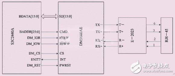
Figure 3 Ethernet interface circuit
4. Software design of network interface module
This system adopts Windows CE operating system and has powerful network support functions. Windows CE supports all network protocols of the Internet including TCP/IP. The network drivers of Windows CE all follow NDIS (Network Driver Interface Specification, network driver interface specification), NDIS provides two abstract layers, used to connect the network driver and the protocol stack. The schematic diagram of the NDIS model is shown in Figure 4.

Figure 4 Schematic diagram of the NDIS model
The driver of DM9000AE under Windows CE is written based on this model, compiled into a dynamic link library, and exists in the form of a DLL file in user mode. The entry function is DriverEntry(). DM9000-driven workflow is shown in Figure 5.
The function of NdisMInitializeWrapper() is to inform NDIS that a small port network card is being initialized. This function is provided in ndis.dll. Then initialize the NDIS40_MINIPORT_CHARACTERISTICS structure variable, mainly to set some callback functions (MiniportInitialize(), MiniportReset(), MiniportInterruptHandler(), MiniportISRHandler(), MiniportQueryInformation(), MiniportSetInformation(), MiniportSend()). Then it is through the NdisMRegisterMiniport() function Use the structure of NDIS40_MINIPORT_CHARACTERISTICS to register with the NDIS system. The next step is MiniportInitialize(), in which there is the initialization of the NIC_DRIVER_OBJECT class, and the EDriverInitialize() function call of this class. In this function, all the initialization operations of dm9000 are fully expanded.
The realization of all the initialization operations of DM9000 is in the dm9000.cpp file, mainly through the DeviceEntry() function. Only one thing is done in the DeviceEntry() function: new an instance of the C_DM9000 class and return. Immediately there is a series of initialization operations for DM9000AE by an instance of C_DM9000 through DeviceSetDefaultSettings(); DeviceSetEepromFormat(); DeviceRetriveConfigurations(hconfig); EDeviceValidateConfigurations() and so on. Then NIC_DRIVER_OBJECT points to DriverStart(). In DriverStart(), C_DM9000 only performs a very simple but most important operation is that it initiates an interrupt in DeviceEnableInterrupt(), and then endless waiting, receiving, sending, and DM9000 starts. Already working.
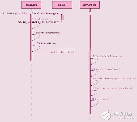
Figure 5 DM9000-driven workflow
After completing the driver, we also need to set the DM9000 registry key in the Platform.reg file:
[HKEY_LOCAL_MACHINECommDM9000]
"DisplayName"="Crystal DM9000 ISA Ethernet Controller"
"Group"="NDIS"
"ImagePath"="DM9000.DLL"
[HKEY_LOCAL_MACHINECommDM9000Linkage]
"Route"=multi_sz: "DM90001"
[HKEY_LOCAL_MACHINECommDM90001Parms]
"BusNumber"=dword:0
"BusType"=dword:0
"InterruptNumber"=dword:3E
"IoBaseAddress"=dword:D3000000
"RxMode" = "PIO"
"NetworkAddress" = "00-01-33-33-33-33"
[HKEY_LOCAL_MACHINECommDM90001ParmsTcpIp]
"EnabLEDHCP"=dword:0
"DefaultGateway"="192.168.126.1"
"UseZeroBroadcast"=dword:0
"IpAddress"="192.168.126.100"
"Subnetmask"="255.255.255.0"
"DNS"="192.168.126.1"
[HKEY_LOCAL_MACHINECommTcpipLinkage]
"Bind"=multi_sz: "ppp", "DM90001"
Connect the designed module to the local local area network, and assign the MAC address and IP address, and use the PC's PINg program to get a response, indicating that the ARP, IP, and ICMP protocols are normal. Use the windows-based application program written by myself to send a connection request to the module, the module returns the correct response information, and the TCP protocol is normal.
ConclusionThis is the end of the related introduction about dm9000ae. I hope this article will give you a more comprehensive understanding of dm9000ae.
Related reading recommendations: DM9000A and baseband signal processing platform combined application
Related reading recommendations: DM9000AE working principle Ethernet interface circuit design
The utility model relates to a medical atomization treatment and humidifying device belonging to the technical field of medical equipment and household appliances.
Professional Medical Atomization manufacturer is located in China, including Medical Vape,Dose Control Vape Pen,Supersonic Wave Vape, etc.
Medical Atomization,Medical Vape,Dose Control Vape Pen,Supersonic Wave Vape
Shenzhen MASON VAP Technology Co., Ltd. , https://www.e-cigarettefactory.com