1 Introduction
High-power LEDs are a core part of semiconductor lighting. With the gradual development of the semiconductor lighting market, lighting products are also accepted by more and more people, and at the same time, higher and higher requirements for reliability. There are many factors involved in the reliability of high power LED lighting systems.
At present, the misunderstanding of people is mainly to attribute reliability completely (or basically) to the reliability of components and the process of manufacturing assembly, ignoring the decisive role of system design and ambient temperature on reliability. According to the statistics of the US Naval Electronics Laboratory, the causes of the failure of the whole machine and their respective percentages are shown in Table 1.
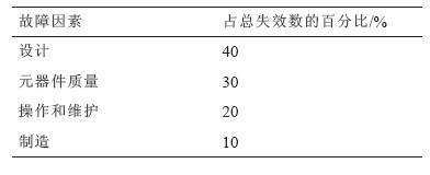
Table 1 Statistics of the causes of the whole machine failure
In the field of civil electronic products, Japanese statistics show that 80% of reliability problems stem from design (Japan's selection of components, quality level determination, component load factor, etc. are also included in the design). The above two data show that the design and components (component selection, quality level determination, component load factor) caused by the failure of the electronic product failure accounted for about 80%.
Since most products will work in complex environments, the most important factor for the product should be selected as the primary consideration when designing the reliability of the product. For example, vibration, impact, etc., which have the greatest impact on the reliability of mechanical products, are the most important factors affecting the reliability of electronic products. Taking equipment as an example, the four main causes of electronic equipment failure are: temperature, vibration, humidity, and dust. Temperature affects electronic devices by up to 60%.
Since there is no test standard for high-power LEDs at present, companies that produce high-power LEDs at home and abroad use the attenuation of luminous flux as the basis for device reliability. This is obviously unreasonable for white LEDs, because only light is considered. The change in brightness does not take into account the change in color temperature. In fact, chromaticity is more important for the reliability of high-power white LEDs. The LED's luminous flux will gradually change with the passage of time. It will not hinder the continued use within a certain range, but the chromaticity changes, its color temperature. Significant changes can also occur, which can affect the aesthetics of the LEDs and even limit their use in some specialty industries. This paper studies and elaborates on the reliability design of high-power LEDs with temperature-related factors.
2 The impact of design on product performance
2.1 The effect of different heat sink design on the temperature of LED chip
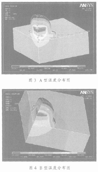
The low thermal resistance design is beneficial to the heat loss of the LED chip, which can effectively guarantee the life of the chip. According to the heat flow model, the heat of the chip can be smoothly transmitted to the heat dissipation substrate, and the thermal resistance is smaller. The following analysis of the relationship between two different heat sink shapes (type A, type B) and heat flow and thermal resistance is shown in Figure 1-6. The type A heat sink has a chip junction temperature of 106 °C under certain conditions, while the B type heat sink has a chip junction temperature of 96 °C under the same conditions. Different heat sink designs make the chip temperature differ by 10 °C. The cause of this temperature difference can be obtained from the heat flow vector analysis. The thermal conductivity of the epoxy glass outside the boss is very low, and the main route of the heat flow is a heat sink made of copper. In Fig. 1, since the heat sink is composed of two bosses, the two bosses are discontinuous in shape, thereby causing the heat flow to be discontinuous as the shape changes.
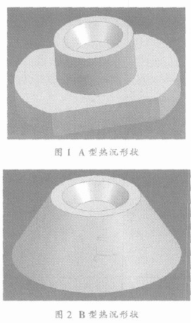
In Fig. 2, since the heat sink has a feature of being large and small in shape, conforming to the law of heat flow propagation, the heat flow can be quickly dissipated, so the temperature of the node is low.
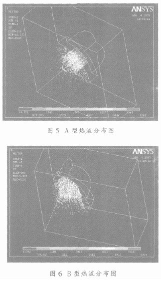
It can be seen that as the heat flow is continuous, the temperature of the chip is effectively improved. At present, there is a derivative structure, which causes the lower heat sink of the LED to directly become a metal-based PCB. The surface of the PCB is processed into a line according to needs, and the heat dissipation utilizes the metal substrate. The structure is simple and has been used in practice. This structure is called C. Type structure. The thermal resistance of the three LEDs was tested using a dynamic electrical test method, as shown in Table 2.
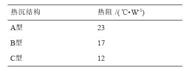
Table 2 Tests LED thermal resistance by dynamic electrical method
2.2 Analysis of the influence of pin soldering temperature on LED color difference
The offset of the color coordinates at the soldering temperature of 350 °C, the soldering time is 4 s, as shown in Figure 7-9.
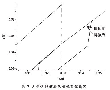
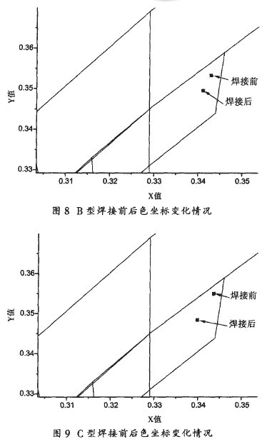
It can be seen from the test results that the color coordinates of the LED after soldering will be differently dispersed in a certain welding condition. The color coordinates of the A-type LEDs before and after soldering are small, and the color coordinates of the B-type and C-type LEDs before and after soldering are changed.
The reason for the large chromatic aberration shift after soldering of B-type and C-type LEDs may be due to the thinner base and the smaller thermal resistance. The thermal shock during soldering causes a certain degree of damage to the LED chip.