With the development of today's society and the improvement of people's material living standards, motor vehicles have entered thousands of households, and the excessive number of vehicles has caused certain difficulties in road management, especially the management of trucks.
This article refers to the address: http://
Although the Highway Bureau has set up a weighing toll station in each section of the road, the truck driver still uses some high-tech means such as unloading, bypassing, or hydraulic devices to escape detection, while the trucks are waiting in line for inspection. Causing road congestion.
Weighing during the driving process of the truck can solve the road traffic problem well, but the configuration of the truck terminal system is not suitable for analyzing and storing a large amount of data, so the detected load data is transmitted to the management system during the driving of the truck. Is a key step in solving the problem.
1 system development environment
This system is developed by Visual C++6.0 combined with SQL Server 2000. Using ODBC to operate the database, VC improves the development environment for database development. ODBC can process the database in a unified way.
In terms of data transmission, the system adopts two transmission modes, GPRS and TCP, to realize the operation of the database management system. Compared with the previous in-vehicle system using GSM transmission, there are some advantages:
1GPRS uses packet switching technology, the length of the transmitted data is not limited, and GSM can only have a maximum of 140 bytes per transmission.
2GPRS is two-way, you can know exactly the success or failure of information transmission, and GSM is one-way.
3GPRS fee is 0.01 yuan / k, that is, 1 cent can transfer data 1024 bytes. GSM sends 0.1 bytes for 0.1 bytes.
4GPRS delay time is very short. GPRS sends 60 bytes delay for about 5s, while GSM has to delay for more than 10s.
2 system structure design
2.1 System module design
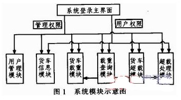
The system has 6 modules, user management module, truck information module, cargo vehicle heavy module, truck overload module, load query module, overload processing module. The schematic diagram of the direct relationship between each module is shown in Figure 1.
2.2 System module function
1) User Management Module This module is used to manage user information. Users are divided into management rights and usage rights. After users enter the management system with administrative rights, they can add, delete and view user information, and can also modify user passwords.
2) Truck Information Module This module is used to manage the basic information of the truck. The user can view the information of the truck. The truck information can be inquired according to the license plate number, owner or registration time of the truck. When the user enters with the management authority, the truck can be added or deleted. information.
3) Cargo truck heavy module This module is used to display the load value of the truck when it is last detected, including the time when the truck is in weight. The user can check the truck's load time and load value according to the license plate number. Information cannot be modified and can only be overwritten by a query.
4) Truck Overload Module This module displays the overload information of the truck, including all historical overload information. Because the overloaded data is protected, the information cannot be added, modified and deleted. Users with any permission can only query this information, which can be obtained by license plate number. Check the overload information of the truck.
5) Planting Query Module This module allows the user to query the current load of the truck and record the queried information into the cargo vehicle database. If the queried information is overloaded, the data will be queried to the truck overload database. go with.
6) Overload Processing Module This module can automatically process the overload information obtained from the vehicle terminal, and process the information to record the information content in the truck overload table. This process is done in the background and does not require the user to operate on it, the user can only see the overloaded information.
3 system database design
A database is a repository for storing and processing data. It is an important part of a system. The database can not only store a single management data, but also provide the data management methods required by users.
The database of this system is designed using SQL Server 2000, which mainly includes 5 aspects of data:
1) User Management Table (TABUSER): User Name (Primary Key), Password, Permission;
2) TABMESSAGE: license plate number (primary key), owner's name, registration time, attribution, truck brand, truck type, cargo weight, overload number, associated characters;
3) Car loading table (TABLOAD): number (primary key), license plate number, date, time, load, overload;
4) TABOVERLOAD: number (primary key), license plate number, overload date, overload time, load;
5) Truck license plate number management module (TABTRUCKNUMBER): license plate sign (primary key), attribution province, attribution.
4 system interface design
The main interface of the system adopts the dialog mode under MFC. The main interface consists of user login management and truck information management, including basic information of trucks, load information and overload information. The Tab control is used to control the display of truck information. The interface graphics are shown in Figure 2.

5 data wireless transmission design
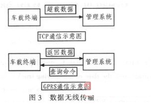
In the system, the data communication of the truck vehicle terminal has two parts. First, the system server actively queries the load information of the vehicle terminal, and after receiving the command, the terminal returns the load information to the system server. Second, the vehicle terminal automatically detects the load information and automatically transmits the overload information to the system server.
When the number of vehicle-mounted terminals is large, the amount of information to be accepted by the system is relatively large, and when the information is actively queried, it takes a certain time to return from the command to the data to the terminal information, so only one communication method will give the information acceptance. Chaos, here active query with GPRS communication, automatically accept TCP communication. As shown in Figure 3.
5.1 GPRS communication
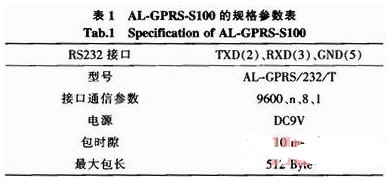
In this system, the product model of the GPRS module used is AL-GPRS-S100, which is connected through the serial port and the terminal. AL-GPRS-5100 is a GPRS transparent transmission terminal (GPRSDTU) designed by Nanjing Wolong Electronic Technology Co., Ltd. It has built-in industrial GPRS module and supports DDP, DNS and VIPS communication modes. Industrial devices with RS232 interface can be wirelessly networked via GPRS without changing any software.
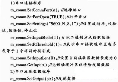
The VC connection serial port should be inserted into the MSComm serial port control. As a serial communication control, it saves a lot of time for the programmer serial communication programming. When the control is loaded into the dialog box, the CMSComm control class is automatically created.
5.2 TCP communication
The system and the vehicle terminal are not a local area network, so the first step is to penetrate the local area network. Here, "TCP punching" is used. Compared with other methods, "TCP punching" has the advantages of easier implementation and high efficiency. The basic principle is: in the local area network. The user first establishes an auxiliary connection with a connection server on the public network, and establishes a TCP direct connection between the calling parties through the assistance of the connection server when the call occurs.
VC performs network communication to insert CSocket class. CSocket supports synchronous operation and can be used separately. Usually, it is used to send and receive data together with CSocketFile and CArchive classes.
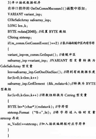
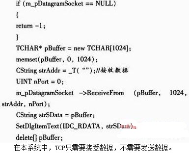
TCP Receive Data Program:
6 data transmission design
6.1 Data transmission design
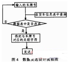
In the load query module, the user sends data when the vehicle is re-queried by the license plate number. The specific process is: when the license plate number of the query is input, the license plate number is inquired in the truck information table (TABMESS AGE), and the corresponding associated character is sent as a query command. The data transmission process is shown in Figure 4.
6.2 Data reception design
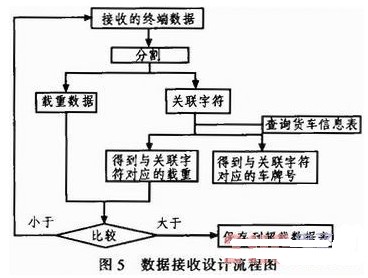
In the load query module and the overload processing module, the system receives data. The specific process is: each data accepted by the system is composed of two parts, the associated characters + goods are heavy, the data is separated first, and the associated characters are in the truck information table (TABMESSAGE). ) Query the corresponding license plate number, and then search according to the license plate number in the cargo vehicle re-meter (TABLOAD), modify or re-create the data of the cargo vehicle.
At the same time, the corresponding load is found in the truck information table (TABMESSAGE) by the associated character, and the load value in the data table and the received load value are compared to determine whether to save the time to the truck overload table (TABOVERLOAD). The data acceptance process is shown in Figure 5.
6.3 dialog interface design
The interface mainly includes a serial port connection part, a transmission data part, and an acceptance data part. The parameter selection of the serial port part is provided by the combo box. The data to be sent is sent in the edit box, and the received data and the time of receiving the data are saved in the list box. The interface of the dialog box is shown in Fig. 6.
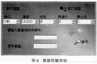
Example: In the truck information table, the license plate number is “Shaan A00000â€, the corresponding associated character is “SHAN0000â€, and the load is “20â€. When inquiring about the load of the goods, enter "Shaan A00000" in the text box, and find the associated character "SHAN0000" through the truck information table.
Send the associated characters. When the character "SHAN000025.000" is accepted, the characters are first divided into "SHAN0000" and "25.000", and the associated characters are searched in the truck information table to obtain the license plate number and the load, and the load and the character "25.000" are compared, and the overload is obtained. Then save the license plate number and the overload character "25.000" to the truck overload table.
7 Conclusion
This paper expounds the implementation idea and management method of designing a management system using Visual C++6.0 and SQL server 2000, and introduces the data communication to the outside world in detail, which realizes the detection of the vehicle terminal and the management of truck information. Meet the requirements of high reliability and high stability.
Parallel Actuator,Mini Electric Actuator,Linear Drive Actuator,Electric Actuator Controller
Kunshan Zeitech Mechanical & Electrical Technology Co., Ltd , https://www.zeithe.com