In the design of a wireless communication signal detection platform based on software radio, after the signal received by the antenna is processed by the inverter and A/D converted, the collected signal is sent to the main control board for data distribution processing through the high-speed channel. The structural block diagram of the system is shown in Figure 1.
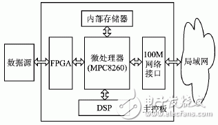
Figure 1 System block diagram of the main control board
The hardware core of the main control board is the embedded microprocessor MPC8260, which is responsible for system software loading, data distribution and interaction with external command control. In software, the high-performance VxWorks embedded real-time operating system is adopted. The RF signal received from the antenna is connected to the FPGA as a data source after being converted by frequency conversion and A/D conversion, and the FPGA performs preprocessing such as intermediate frequency conversion and channel estimation on the received data, and then transfers the data to the local memory under the control of the CPU. Finally, the CPU quickly distributes the data after it is packaged. Therefore, transferring 40 to 50 Mbps high-speed data streams from the FPGA to the CPU becomes a key to system design.
If each byte of data is transferred by the CPU, then whether the interrupt driver or program query, the data transfer rate will be very low, can not meet the system requirements. Compared with the general program control transfer mode, DMA (Direct Memory Access) has the advantages of high data transfer speed, short I/O response time, and small CPU overhead. Therefore, the DMA transfer mode is selected so that the data in the FPGA is not It is directly stored in the local memory after being transferred by the internal registers of the CPU. MPC8260 supports a variety of DMA implementations, which are applicable to different data transmission source/destination devices, different transmission data block sizes and storage modes. Therefore, it is necessary to design a suitable DMA transmission interface according to the system characteristics of the main control board.
1 MPC8260 DMA system structure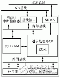
Figure 2 CPM block diagram
The MPC8260 is an embedded PowerPC microprocessor designed by Freescale for the data communications field. It has a dual-core architecture: a high-performance MPC603e 64-bit RISC microprocessor core and a 32-bit RISC communication designed for communication. Processing module (CommunicaTIon Processor Module, CPM). CPM can share most of the peripheral communication tasks of the PowerPC core, including two DMA controllers, namely Serial Direct Memory Access (SDMA), so the architecture of this dual processor is more than a single processing. The device has stronger communication control functions. The block diagram of CPM is shown in Figure 2. In addition to the PowerPC core and CPM, the MPC8260 includes a flexible System Interface Unit (SIU) that is primarily used to control the interface to the external bus.
In FIG. 2, in addition to the SDMA module, the CPM includes a communication controller (Communica TIons Processor, CP), a dual port RAM, and some serial peripheral device control interfaces. SDMA is connected to the 60x bus, local bus, and has direct access to the dual port RAM inside the CPM. The CP uses these two SDMAs to provide two virtual SDMA channels for each peripheral serial controller: one for the input and one for the output. At the same time, CPM also uses these two physical SDMA channels to simulate four programmable, independent DMA (Independent DMA, IDMA) channels for data transfer between memory-memory and peripheral-memory.
The FPGA and SDRAM on the main control board are all attached to the 60x bus of the MPC8260, so IDMA can only be used to achieve DMA transfer between the two. According to different triggering modes of transmission initiation, IDMA can be divided into two types: IDMA transmission controlled by handshake signal and IDMA transmission controlled by CP command. The following describes the characteristics of the two methods.
1.1 IDMA transmission controlled by handshake signalThe IDMA transmission controlled by the handshake signal is mainly used for data transmission between the peripheral and the memory. Each IDMA channel has three handshake signals for transmission handshake control: DMA request signal DREQ[1~4], DMA response signal DACK[1~4], and DMA end signal DONE[1~4].
In this way, the PowerPC core only needs to participate in the initialization of the IDMA channel. After the transmission process, the CP controls the data transmission and reception according to the channel parameter setting and the handshake signal to release the kernel to the maximum extent. The disadvantages of handshake control are:
1 The data in SDRAM and the data synchronization of MPC8260 are more complicated.
2 Bus arbitration is performed after each request signal is issued, and only the peripheral port size or 32-bit data can be transmitted at a time after the bus usage right is obtained, and the bus utilization is low.
3 The handshake control logic and timing are complex, which increases the burden of FPGA internal control logic design.
Although this transmission mode basically does not occupy the core resources, due to the limited bus bandwidth and low utilization rate, under continuous high-speed communication conditions, the kernel may not be able to obtain the bus usage right for a long time and is always in a waiting state. Therefore, the IDMA controlled by the handshake signal is generally only applicable to transmissions initiated by peripherals that are not too frequent.
1.2 IDMA transmission controlled by CP commandThe MDMA of the MPC8260 can also be internally triggered by writing a START_IDMA command to the CP command register. The PowerPC core is released each time the transfer is initiated, and the parameters such as the source address, destination address, and transmission data length of the transfer are controlled by the CP according to the information initialized on the IDMA channel. The maximum length of each transfer is 4 GB.
We are a legal e-cigarette trader in China, We can provide you with IGET Disposable Vape, vape 600puffs/1200puffs/1800puffs/2300puffs/2600puffs/3000puffs/3500puffs/4000puffs/5000puffs.supplier the largest selection of disposable vape from China. and deliver to the destination just cost 7-15davs. Over 1000 products available now! High-quality
Sufficient supply and favorable price, If you need to pick up goods wholesale, don't miss us


IGET Vape,IGET Disposable Vape 1500Puffs,XXL IGET Disposable E Cigarette,Pen style disposable electronic cigarettes
tsvape , https://www.tsvaping.com