With the rise in oil prices and the increase in environmental protection requirements, electric power has become an important direction for future car development. For battery-powered all-electric power systems or for engine and battery hybrid systems, power management system design is an important factor in vehicle performance. The overall vehicle design and external environment must be considered in design, in order to save power. It is also necessary to design a certain control strategy to ensure the best use of the power supply. Therefore, it is necessary to conduct an in-depth discussion on the power management system of all-electric vehicles.
1, the importance of electric vehicle energy management The main purpose of electric vehicle power management is to make full use of the fuel's combustion efficiency, to make the engine work near the best working point, and to adjust the energy storage and output of the electric motor and battery to adjust the running condition of the vehicle and the external road conditions in time. Matching relationship. After more than ten years of development, the power system design of electric vehicles is currently the most practical and has a commercial operation mode, only hybrid vehicles. The hybrid system assembly has evolved from the original engine and motor discrete structure to the integrated structure of the engine motor and transmission, namely the integrated hybrid powertrain system. Therefore, only the power management of the hybrid system is considered here. Power management of hybrid systems, functionally, needs to achieve the following two goals:
(1) Guarantee the optimal working condition of the engine to avoid inefficient operation of the engine. The engine can usually be adjusted to operate stably around the optimum operating point, and the output of the battery and the motor can be adjusted to adapt to various external road conditions. For example, when the vehicle is in a low speed, coasting, idle condition, the motor is driven by the battery pack, and the engine-motor group and the battery pack collectively supply electric power to the motor when the vehicle is started, accelerated, or climbed. In this way, the engine is prevented from idling and low-speed operation, thereby improving the efficiency of the engine, not only reducing exhaust emissions, but also saving power.
(2) Make full use of the inertial energy of the vehicle. When the vehicle is decelerating, braking, or traveling downhill, the motor is driven by the inertial force of the wheel. At this time, the electric motor becomes a generator, which can charge the reverse battery and save fuel.
Statistics show that under the road conditions of more than 80%, an ordinary car only uses 40% of the power potential, and will fall to 25% in the urban area, while electric vehicles with power optimization management, such as Toyota's Prius, Its power has exceeded the level of its class, fuel savings of 75%.
The power management of electric vehicles needs to monitor the working conditions of the engine, electric motor, battery, vehicle running speed, driving resistance data and driver's operation at any time, and can automatically control the energy-saving device or circuit after intelligent processing according to the above data. Therefore, it is necessary to first solve the connection mode of the component operating state sensor related to energy consumption and energy conversion.
At present, the data communication between the internal measurement and execution components of the automobile mainly adopts the CAN bus technology. The bus technology was first introduced by the German company BOSCH, and is mainly used to solve the data exchange problem between many control and test instruments in modern automobiles. The electric vehicle power management system developed by CAN bus not only has high communication speed, accuracy, high reliability, but also is easy to be compatible with the vehicle control network, sharing sensor information, calculation information and operation status of each control unit, and on-board Or provide a basic platform for vehicle fault diagnosis, etc., so in this topic, the CAN bus is used as the basic communication technology for power management.
The CAN bus-based energy management network topology formed by the energy consumption of the chassis part of the electric vehicle is shown in Figure 1. It includes the brake energy conversion device, powertrain, battery management, motor controller, and driving resistance test. Several lower critical monitoring nodes and a higher-level master node composed of an on-board computer system.
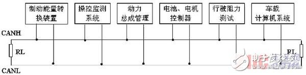
Figure 1 Energy management network topology based on CAN bus
The brake energy conversion device works in conjunction with the driver's control monitoring system and the battery motor controller. When the driver steps on the brake pedal, the brake motor is first brought close to the rotating device to be braked, such as the drive shaft, consuming the inertial energy of the vehicle and converted into electric energy, and the control monitoring system monitors the brake pedal when the battery is charged. The circuit is adjusted to realize the storage of electrical energy transmitted by the brake motor.
The powertrain system is mainly used to optimize the operation of the engine operating conditions. In the normal exercise situation, the energy of the engine is divided into two ways, one way is transmitted to the vehicle transmission and propulsion system, the driving vehicle is normally exercised, and the other road drives the motor to work and supplies power to the battery. At this time, the auxiliary power system composed of the motor and the battery is equivalent to an energy regulating device, and the battery motor controller and the driving resistance testing device are used to adjust and distribute the output energy of the two engines according to changes in the external road conditions.
Through the CAN bus, the upper master node composed of the on-board computer system connects the entire energy management and control network, and through the special software system, data acquisition, data analysis and control strategy output are realized, which realizes the relationship between the external driving resistance and the engine energy adjustment. Optimize the matching to realize the energy conversion and utilization inside the vehicle, and realize the regulation of energy saving, energy storage and supplementary energy of the motor and battery system.
The JUK universal Screw Terminal Block series has the typical features which are decisive for practical applications:
l The universal foot allows the terminal blocks to be easily snapped onto the NS35 or NS32 DIN Rail with G shape.
l Closed screw guide holes ensure screwdriver operation perfect.
l For terminal block with different wire cross-sectional areas, complete accessories are available, such as end plates, partition plates, etc.
l Potential distribution achieved by fixed bridges in the terminal center or insertion bridges in the clamping space.
l Same shape and pitch Grounding Terminal Blocks as the JUK universal series.
l Adopt ZB marker strip system,achieve unified identification.
Screw Cage Connection Termianls,Screw Installation Terminal Block,Din Rail Double Deck Terminal Block,4 Connector Clamp Terminal Block
Wonke Electric CO.,Ltd. , https://www.wkdq-electric.com