Braking performance is one of the key indicators for vehicle safety testing. The methods of inspection include road test method and bench method. According to the provisions of GB7258-1997, the road test method mainly tests the braking performance of the vehicle on the road. The parameters detected include the braking distance; the average deceleration issued; the brake pedal force; the braking coordination time, etc. [1] [3].
This article refers to the address: http://
The vehicle braking performance is tested on the road. The test instrument is mainly the vehicle speed sensor. The braking performance of the vehicle is evaluated by the change of the vehicle speed when the car brakes on the road. Most commonly used brake performance testers are sensors mounted on the body, which is difficult to use and maintain. In the detection of motor vehicle braking performance and traffic accidents, as well as in the vehicle repair industry, one can quickly measure the braking distance and braking time, which is convenient, intelligent, high-precision, cost-effective, and does not require mechanical and mechanical Automotive brake performance testers with electrical installation connections are particularly important. In order to improve the automation level of detection and the accuracy of detection, a vehicle braking performance detector based on C8051F206 single chip microcomputer and acceleration sensor was designed.
1 How the brake detector works
The braking process of the car is: when the car is driving on a smooth road at a prescribed initial speed, the driver steps the brakes to the end until the car stops. The braking performance tester completes the detection of the braking distance and the braking time. The working principle is that the acceleration sensor is the main detecting component, and the acceleration sensor is used to decelerate during braking.
The measurement is performed by the single-chip computer to calculate the braking distance and braking time. The system mainly includes three processes: the judgment of braking start and the data acquisition process; the processing and analysis process of data; Display process of dynamic distance and braking time. The acceleration and instantaneous speed curves of the vehicle braking process are shown in Figure 1:
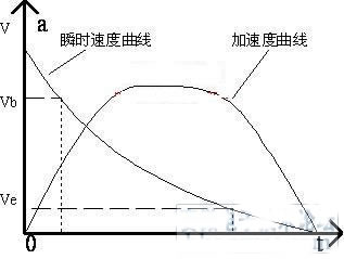
Figure 1 Acceleration and instantaneous velocity curves of the vehicle braking process
1.1 Brake start judgment and data acquisition process
Since the tester does not have any electrical and mechanical hard connection with the motor vehicle, the timing of the braking must be judged by the software based on the output of the sensor to determine the acquisition and storage of the data.
1.2 Data processing and analysis process
1.2.1 Calculation of braking distance:
The braking distance is the distance that the brake pedal is stepped on at the specified initial speed, from the time the foot touches the brake pedal to when the vehicle stops. Since the real-time vehicle speed has been obtained, the braking distance is the integral of the real-time vehicle speed.
![]() (1)
(1)
Where S is the braking distance (m); v is the initial braking speed (km/h); t is the coordination time (s); .i is the braking deceleration (m/s2).
1.2.2 Calculation of the average deceleration issued
According to GB7358-1997, the formula for calculating the average deceleration (MFDD) that is fully issued is as follows:
![]() m/s2 (2)
m/s2 (2)
Where, V is the initial brake speed (km/h) of the test vehicle; Vb is the test speed (km/h) of 0.8V; Ve is the test speed (km/h) of 0.1V; Sb is the test speed from Vv to Vb. Travel distance (m); Se is the travel distance (m) [2] of the test vehicle speed from V to Ve.
2 hardware design of brake detector
The brake detector consists of accelerometer, brake pedal force sensor and data acquisition, microprocessor C8051F206, LCD display/keyboard, micro printer, serial communication and data storage. The hardware block diagram is shown in Figure 2:
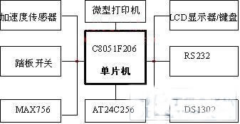
Figure 2 hardware block diagram
2.1 Microprocessor selection
After analysis, we decided to use C8051F206 microcontroller. The C8051F206 chip has the following advantages: First, it runs fast. The chip adopts a pipeline instruction structure. The execution time of 70% instruction is 1 or 2 system clock cycles. When operating at the maximum system clock frequency of 25MHz, the execution speed can reach 25MIPS. Second, there are more ADC input ports. Up to 32 12-bit ADC inputs can be configured as ADC inputs. And the sampling rate is 100ksps, and it is not necessary to add an ADC chip to meet the needs; the third is that the on-chip storage space is large. The chip has 8KB of FLASH memory, 256 B data SRAM and 1024 B of XRAM; the fourth is convenient for debugging. JTAG debugging is supported in this slice. Fifth, the security mechanism is reliable. The chip has 7 kinds of reset sources, which greatly improves the operation reliability, and uses the JTAG port programming to encrypt the chip, which improves the confidentiality of the system. Sixth, it has an industrial working temperature range, which can meet the requirements of the system.
2.2 Acceleration sensor selection
The acceleration sensor selects Motorola's 2260D. The sensor uses a single 5 volt power supply with a measurement range of ±1.5g. The corresponding output DC voltage range is 1.3-3.7 volts. The linearity is good. It can be easily connected to the MCU without amplification.
2.3 LCD display selection
The LCD display selects the LM3033B, which is driven by the ST7920 controller with Chinese character library. The main features are: built-in Chinese character library, providing 8192 16×16 dot matrix Chinese characters (simplified), built-in 128 16×8 dot matrix characters, drawing display screen providing a 64×256 dot drawing area GDRAM, and CGRAM providing 2 groups. Software programmable 16 × 16 dot matrix wording function, single 5V power supply, display resolution: 128 × 64 points.
2.4 Data Storage and Time Chip Selection
The instrument is a portable road test instrument, so it requires a large amount of data storage. In order to facilitate interface and data storage, AT24C256 non-volatile serial port memory is selected. Used to save up to 256 test results. Time chip selection DS1302 is used to save the date and time of each test.
3 system software design system software adopts modular design, menu management, including: system initialization, main menu management, coefficient calibration, parameter setting, printing, communication, measurement and other modules. System software block diagram shown in Figure 3:
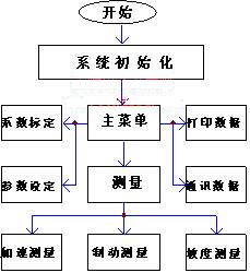
Figure 3 software composition block diagram
4 Conclusion
The innovation of this system is as follows: (1) Using the acceleration sensor 2260D, the integral algorithm is used to measure the braking distance and the instantaneous speed, which avoids the hard connection between the instrument and the vehicle under test, and improves the convenience of the instrument. (2) Select C8051F206 single-chip microcomputer and high-precision components to improve the test accuracy; (3) Select Chinese LCD display and touch keyboard, which is intuitive and easy to operate. At present, the instrument has been mass produced.
references:
[1] Wang Xiang, Development of an Automobile Brake Performance Tester, Sensor Technology, 2004, 23-2: 24-26
[2] Cao Jian, Detection of Vehicle Braking Performance, Zhongnan Automobile Transportation, 1998, 6-2: 13-14
[3] Chen Jianping, Design and Implementation of Automotive Safety Monitoring System, Microcomputer Information, 2006, 12-2: 229-231
10L Agriculture Drone,Spraying Drone,Uav Folding Drone,Uav Drone Crop Sprayer
Xuzhou Jitian Intelligent Equipment Co. Ltd , https://www.jitianequipment.com