This article refers to the address: http://
Application backgroundIn portable devices, it is common to share a USB I/O interface with a UART (Universal Asynchronous Receiver Transmitter) signal path. The designer used an analog switch for this purpose, as shown in Figure 1.
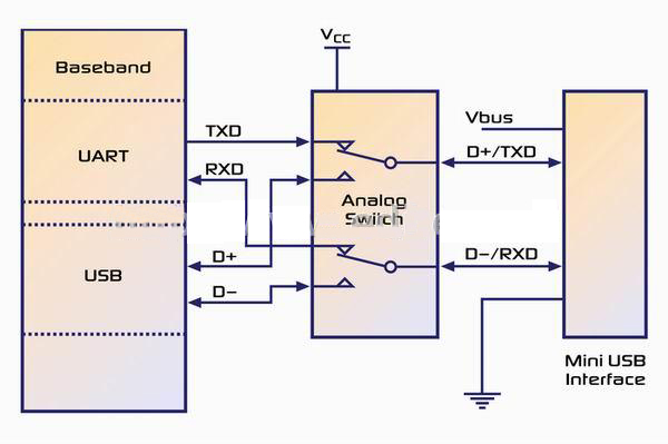
figure 1
The UART interface is used for system software updates, so users will rarely use this feature, thus avoiding the extra space and additional cost of the external I/O connector. For ease of debugging and development, designers often prefer to have such applications share data channels with USB ports.
Another popular trend is to share a micro USB connector between the USB signal and the audio signal. Figure 2 shows the most common application sharing methods.
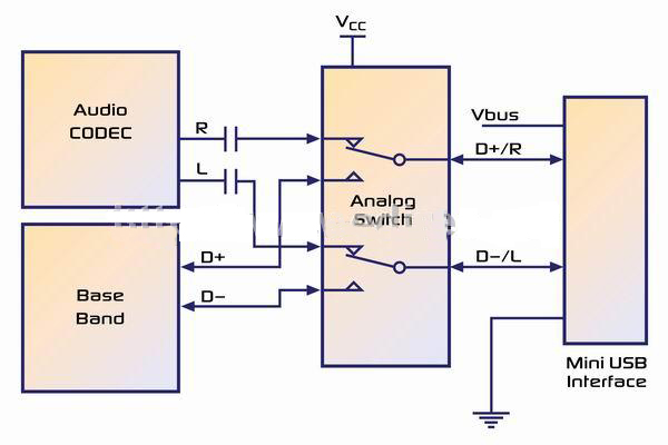
figure 2
In this application, a negative signal will appear after the audio signal path of the capacitor. However, a normal single-supply system cannot receive a negative signal, which may cause unexpected leakage or damage. In some cases, the analog switch can withstand negative signals without crashing, but the negative swing of the signal can cause unpredictable channel crosstalk, greatly reducing the OFF isolation performance, and may even cause the channel that should be turned off to be on.
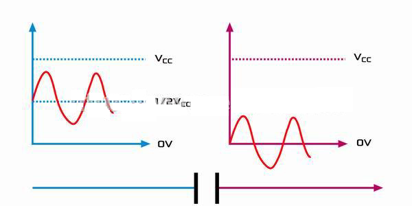
image 3
Low-power robust I/O design challenges
There is a concern with UART/USB shared applications that the signal level may exceed the supply voltage of the internal system. Battery-powered device power supplies typically have an I/O voltage of 3.3V. If we use this I/O voltage as the power source for the analog switch, the USB low-speed/full-speed signal level is between 3.0 and 3.6V, and there is a risk that the input signal level will exceed the supply voltage when the system is operating. Another issue is how to protect the system while the system is in a "power off" state. Typically, this requires a stable power supply to achieve a high impedance state of the analog switch.
There are two solutions to these problems. One is to use the battery power supply as the analog switch VCC, but this depends on the discharge limit of the system, that is, if the system allows the battery discharge voltage to be below 3.6V (which is unfortunately often the case), the first problem remains unresolved. . In addition, most of the time, the battery supply voltage is higher than the system's I / O voltage (3.3V), which means that the level of the logic select pin may be much lower than the power supply voltage, which may cause a large current leakage. . Therefore, in order to prevent current leakage, a level shift IC needs to be added to the logic select pin. Figure 4 illustrates this.
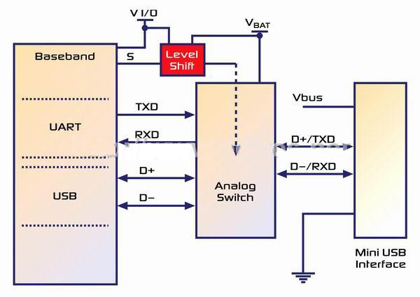
Figure 4
The second solution is shown in Figure 5.
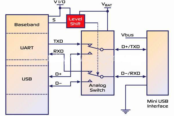
Figure 5
This power solution ensures that the system always has power at all times (regardless of power-up or power-off, whether the USB cable is plugged in). The only limitation of this solution is the cost of additional components. The last problem with this application is often overlooked: the requirement for USB short-circuit tolerance.
Short circuit withstand capability
The USB transceiver must be able to withstand D+ and/or D- to VBUS, GND, and other data lines, or at least 24 hours of continuous shorting in the cable shielded enclosure at the connector plug without degrading performance. It is recommended that the transceiver be designed to withstand such uncertain short-circuit faults. In the case of a short circuit, the device must be protected from damage when the transmission and reception times are each half (all supported speeds). There is a symmetrical signal during transmission, switching between high and low levels. The short-circuit withstand capability of the system must be guaranteed when VBUS is at its maximum (5.25V). These AC and short circuit requirements are recommended as the qualification criteria for long-term reliability of the device. That is the USB2.0 specification.
Another important factor to consider is ESD (electrostatic discharge) protection. Since the I/O port is extremely susceptible to ESD, it is highly recommended to provide additional ESD protection. If the USB signal path is high speed (480M bps), the parasitic capacitance is preferably less than 1pF to minimize bus load, which would otherwise adversely affect the eye diagram test results. In audio/USB sharing applications, there is also the challenge of a negative wobble signal. One way to avoid this is to place the capacitor in the headphone cable. However, for better audio low-band response, the capacitor should be as large as possible, which increases size and cost. Another way to solve this problem is to use a negative swing audio amplifier in the design (the audio output signal swings directly up and down based on GND).
Fairchild's innovative multimedia switches, the FSA201 and FSA221, address these issues (FSA201 for full-speed USB and FSA221 for high-speed USB).
 Align=center>
 Figure 6
FS USB source FS USB source
AUDIO CODEC audio codec
Device ID recognition
MINI USB CONNECTOR Micro USB Connector
With the FSA201 and FSA221, internal logic control automatically switches power between VAUDIO and VBUS and meets USB short-circuit withstand capability. These switches automatically put all ports in a high impedance state when VAUDIO = 0. In addition, the R/L channel can receive a negative swing signal as low as VAUDIO-7.0V (if Vaudio=3.3V, it can receive a 3.3V~-3.7V signal) with very high isolation. It features low ICCT characteristics, allows for higher supply voltages on VAUDIO, and allows normal I/O voltage level control signal inputs with leakage less than 10uA. These switches integrate 8KV ESD protection (HBM mode), making them ideal for I/O sharing applications. All of these features greatly simplify the system's I/O design while protecting the port from damage.
to sum up
As the market trend is to integrate more and more multimedia functions into portable devices that are becoming thinner and smaller, analog switches have a new role in hybrid signal conversion, system protection and intelligent detection. These switches are not only an important bridge to connect different modules in a portable application, but also have the functions of signal sharing, isolation and protection. A new generation of analog switches, such as the FSA201 and FSA221, offer designers significant advantages. With these switches that combine high performance, robust ESD protection and ultra-compact packaging, designers can simplify designs, reduce component count, reduce costs, and bring products to market faster. As a result, designers are able to spend more time on design without having to worry about choosing different chipsets and updating processors to handle the tough design challenges of port sharing.
Many consumers are worried that the record of the driving recorder is not clear at night or in dim conditions,
so they are more inclined to buy a driving recorder with good night vision effect.
Here I want to popularize it for everyone. A high-resolution driving recorder does not necessarily have a good night vision effect.
The night vision effect depends more on the size of the aperture. The larger the aperture, the better the night vision effect.
Hikvision`s night vision driving recorder not only matches the high-definition resolution with a large aperture,
but also adopts advanced product development solutions, such as owl night vision technology,
to allow the Dash Cam to record in high-definition at night.
dash cam night vision,night HD dash cam,HD night cam,night vision dash cam
Hangzhou Hikauto Technology Co.,Ltd , https://www.hikmotorstore.com