In order to prevent the height sensor-related faults during the use of unmanned helicopters and reduce the possibility of flight safety accidents, a flight fault occurred in the execution of a certain type of unmanned helicopter, combined with the working principle of the height sensor and The application of man-machine flight control uses the fault tree method in reliability analysis to analyze the existing fault causes. Finally, a solution to the problem of height sensor failure occurred was proposed.
Small unmanned helicopters have broad application prospects in the civil field and national defense construction, and their safety and reliability have also received more and more attention. The prerequisite for ensuring the safe flight of micro-miniature unmanned helicopters is the reliability of the on-board sensor system. The onboard sensor is the basic component of the flight control system and one of the most prone to failures. Because the airborne sensor works in a high temperature and strong vibration environment, it is easy to cause the sensor performance to be unstable and cause a malfunction. The altimeter is an important sensor in the aircraft. It plays an important role in the safe flight and autonomous control of the aircraft. In the daily use of unmanned helicopters, flight accidents caused by the failure of the height sensor have occurred. This paper studies the application of height sensors in unmanned helicopters, analyzes the causes of this accident, and proposes solutions.
1 The role of height sensors in flight control of unmanned helicopters
1.1 Commonly used measurement height methods There are many methods for measuring the flying height. According to different measurement principles, the flying height under different definitions can be measured. Commonly used are the following:
(1) A method of measuring the flying height using the radio wave reflection characteristic is to convert the height measurement into a measurement of time. Electromagnetic waves propagate in the air at the speed of light c and can be reflected when hitting the ground. Therefore, after the radio transmitter mounted on the aircraft transmits electromagnetic waves to the ground, the antenna of the receiver on the aircraft receives the reflected wave at Δt time, and the true flying height H of the aircraft can be measured according to Δt.
(2) The flying height is measured by measuring the linear acceleration of the vertical ground motion of the aircraft. The relationship between the distance (height) h, the speed V and the acceleration ay of the vertical motion of the aircraft relative to the ground is as shown in equation (1): ![]()
(3) Measuring the flight height by measuring the atmospheric parameters. In the gravity field, the atmospheric pressure and atmospheric density decrease with height, although the respective laws of change are different, but they are all rule-based, so The flying height is measured indirectly by measuring atmospheric pressure or atmospheric density.
The height sensor used on the drone used is the sensor of the third type. It is a HPA200-W2DB height sensor manufactured by Honeywell. It is a silicon piezoresistive pressure sensor with high sensitivity, simple follow-up circuit, high degree of integration, high comprehensive precision, no transmission parts, stable performance and reliability. High, small size, light weight, and easy to use, it is suitable for applications on drones.
1.2 Working principle of height sensor In order to uniformly evaluate the dynamic characteristics of the aircraft, compare and calculate the flight state, the world's major aviation countries have developed a hypothetical standard atmospheric model. The model excludes the influence of geographical coordinates, seasons and day and night on the physical properties of the atmosphere. It is believed that the temperature, density and pressure of the atmosphere vary with height according to a fixed law. Therefore, the altitude of the UAV can be calculated using the atmospheric pressure value.
Standard air pressure --- height formula is: ![]()
Where: PH is the pressure at height H; β is the temperature gradient; g is the acceleration of gravity; R is the gas constant for air; Tb, Hb, Pb are the atmospheric temperature, standard pressure height and pressure of the corresponding layer in the high stratification lower limit. The system discussed in this paper is applied to a small unmanned aerial vehicle flying at low altitude. The flying height is less than 11km, which can take β=-6.5×10⁻³ k·m-1, g=9.8 06 65 m·s- 2, R = 287.052 87 m2 · k-1 · s-2; according to the method of atmospheric temperature, height and pressure stratification proposed in the relevant literature, the values ​​of Tb, Hb, Pb are selected.
After measuring the air pressure value, substituting (2) can calculate the flying height of the drone.
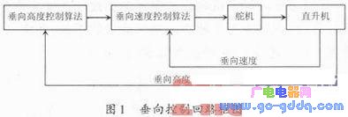
1.3 The application of the height sensor data in the flight control system The vertical control of the helicopter is realized by controlling the lift of the main rotor. The height information and vertical speed information of the vertical control are from the height sensor, and the ground is recorded. The air pressure is compared with the helicopter's flight pressure value. The higher the pressure is, the lower the pressure is. The difference between the two can be used to calculate the current height of the helicopter. Through the change of height, the vertical speed can be calculated. Once the height sensor fails, the vertical control system of the unmanned helicopter will cause problems, resulting in serious accidents. The vertical control loop is shown in Figure 1.
2 Height sensor failure phenomenon and cause analysis When a certain type of unmanned helicopter is flying, the height display failure suddenly occurs, and the unmanned helicopter loses control. The screenshot is shown in Figure 2.
The height sensor height data of the accident point is intercepted, the data is analyzed, and the height variation curve is plotted as shown in FIG.
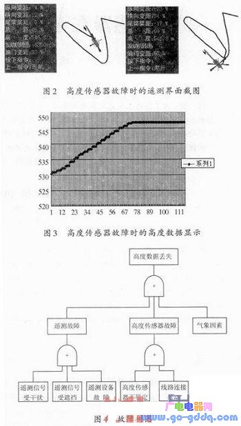
It can be seen from Fig. 2 and Fig. 3 that the unmanned helicopter suddenly loses the height data during the flight. According to the fault tree method in the reliability analysis, the reasons for the possible failure are shown in Fig. 4.
Monochrome Lcd-Cog,Graphics Lcd Display,Transmissive Cog Lcd Module,Positive Cog Lcd Module
Huangshan Kaichi Technology Co.,Ltd , https://www.kaichitech.com