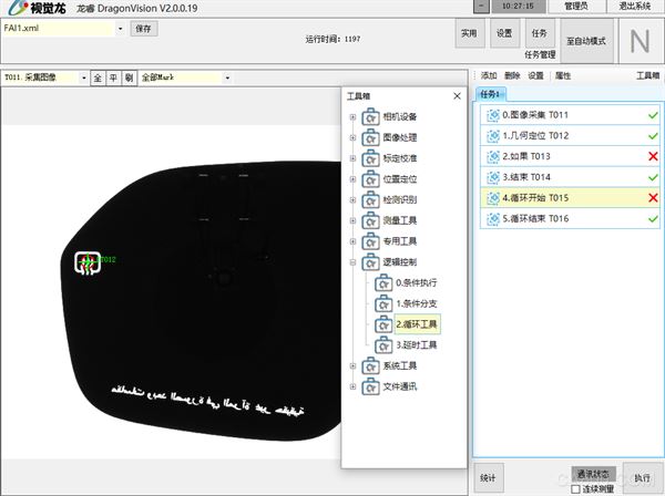
1. Overview of Longrui Vision Software
Longrui is a set of comprehensive vision processing standard software system with configurable tasks independently developed by Shenzhen Vision Dragon Technology Co., Ltd. It supports a variety of gigabit network cameras, free configuration of detection tasks, multi-task, multi-station detection; toolkit covers positioning, measurement, detection, search, logical judgment, and supports strings, multi-results, parallel output and image operations, etc. , has been applied in a number of visual positioning, size measurement, defect detection projects.
2. Project Solutions
Hardware solution:
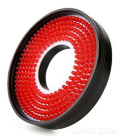
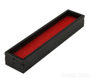
1. Light source selection
Common light sources
The function of the light source and the selection method
The role of lighting in machine vision applications is to maximize the contrast between the features that need to be observed and the image features that need to be ignored, so that the features can be easily distinguished, and the second is to maintain sufficient brightness to exclude the interference of external light on vision. , so as to ensure the stability of the drawing. Choose the light source from the following two aspects.
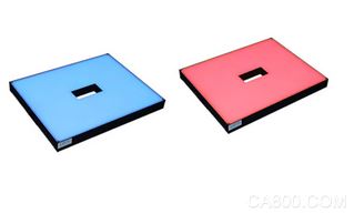
The color of the light source: We see an object as a certain color because it reflects the corresponding spectrum. When we shoot an object, if we want to make a certain color white, we have to use a light source with the same or similar color (the wavelength of light is the same or close), and if we want to make it black, we need to choose a wavelength different from the target color. larger light source. Since the background of this case is blue and the detection equipment is white, the background needs to be marked as black, so the color of the light source is red, and the red LED has a long life, stability and low price. More importantly, the wavelength of the red LED is closer to the sensitivity peak of the sensor. .
Shape of light source: The light sources commonly used in machine vision include ring light source, strip light source, backlight source, coaxial light source, etc. Considering the convenience of mechanism installation and the need for uniform illumination, this case chooses a medium-hole red backlight.
2. Camera selection
Industrial cameras can be divided into black and white cameras and color cameras according to the color of the phase, can be divided into line scan cameras and area scan cameras according to the scanning method, and can be divided into CCD cameras and CMOS cameras according to the chip type.
The camera selection should first clarify the project requirements, determine the accuracy requirements of the inspection products, determine the size of the field of view that the camera looks at, determine the speed of the detected objects, and determine whether it is dynamic detection or static detection. Next, determine the hardware type and select the camera data transmission interface: 1394, Gige (Gigabit Ethernet), USB, camera link. Then select the appropriate camera chip size according to the matching with the lens (the maximum compatible chip size of the lens is greater than or equal to the chip size of the camera) and the interface type (C or CS) with the lens. The error of the vision system hardware is inevitable, and the error between one or two pixels is generally guaranteed, so through the calculation formula: accuracy = field of view (length or width) ÷ camera pixel (length or width) For example: suppose the field of view is 100*60, the accuracy requirement is 0.1. Considering the hardware error, the accuracy is generally 0.05 when selecting the model, then the pixels on the long side of the camera=100÷0.05=2000, and the pixels on the short side are 60÷0.05=1200, then only the theoretical resolution is required. A camera with a ratio greater than or equal to 2000*1200 pixels can meet the needs.
This project selects a camera with a resolution of 500 (2500pix*2000pix), a frame rate of 14 frames, a communication interface of Gige (Gigabit Ethernet), and a C interface with the lens interface according to the relationship between field of view and accuracy.
3. Lens selection
1. Do you need to use a telecentric lens?
Telecentric lenses are generally considered in precision dimensional measurements. The main function of the telecentric lens is to correct the parallax of traditional industrial lenses. It can be within a certain object distance range, so that the magnification of the obtained image will not change. It is divided into object-side telecentricity, image-side telecentricity and bilateral Telecentric, where optical magnification = camera chip size / field of view size = chip (V) or (H) size / field of view (V) or (H), the larger the field of view, the smaller the magnification. In general, telecentric lenses have fixed focal length and working distance, and some telecentric lenses are bulky and heavy, so it is necessary to understand the customer's requirements for field of view, working distance, space constraints, and motion control in detail. to determine the lens model that needs to be selected.
2. The depth of field of the lens
The spatial distance that the camera can clearly image in the vertical direction is called the depth of field. The shorter the focal length, the greater the depth of field; the smaller the aperture, the greater the depth of field; the farther the lens is from the object, the greater the depth of field; the larger the camera chip pixel, the greater the depth of field.
3. The maximum compatible chip size of the lens
The maximum compatible chip size of the machine vision lens must be greater than or equal to the chip size of the camera, otherwise serious distortion and aberration will be caused.
4. Interface of machine vision lens
Both machine vision lens mounts and camera mounts are divided into C, CS, F and other larger size mount types. The camera and the lens are complementary, that is, the C-mount camera can only use the C-mount lens, and the CS-mount camera can use the CS-mount lens and the C-mount lens with a 5mm ring.
5. The focal length of the machine vision lens
The selection of the focal length of the lens is based on the formula focal length f = working distance × CCD chip size ( H or V) / FOV ( H or V) to select a lens with a suitable focal length.
According to the calculation formula of focal length, this project selects a fixed focal length lens with a focal length of 8mm, a C-mount interface, and a maximum compatible chip size of 2/3.
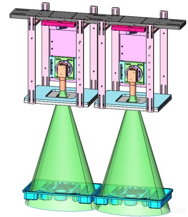
Project visual installation structure diagram
Software Solutions:
The software uses Longrui standard vision software to perform defect detection tasks, requiring detection of the absence and dislocation of medical devices in the material box. The software uses a combination of the Blob Analyzer tool and the Locator tool for defect detection, where the Locator tool is used to locate and detect instruments suitable for template and define the search box of the Blob Analyzer tool. The Blob Analyzer tool is used to detect smaller instruments and some partial deletions. Finally, an evaluation tool is used to evaluate the used detection tool to determine OK or NG, and then the result is sent to the PLC for processing.
Plaque Analysis Tools:
1. The concept of Blob Analyzer
Blob Analyzer uses image segmentation algorithms to process pixel information in the selected rectangular search box, and can find valid blobs according to user-defined conditions.
2. Image segmentation
Blobs represent specific regions within an image that are characterized by grayscale values ​​within a specific range. For each new image Blob Analyzer generates a histogram representing the distribution of pixel values ​​within a rectangular search box, and the image segmentation algorithm provides a thresholding function that allows Blob Analyzer to classify areas of the image into two categories: blobs and backgrounds.
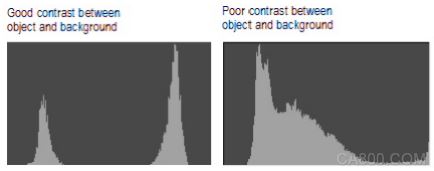
3. Histogram
The histogram provides the distribution of all pixel values ​​in the rectangular search box selected by the Blob Analyzer, with pixel values ​​ranging from 0 (black) to 255 (white). Images that are well suited for blob detection usually present a bimodal histogram, i.e. have two cusps
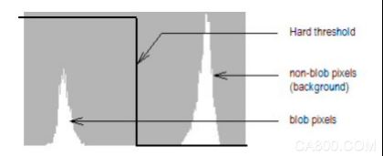
4. Threshold
Thresholding is used to segment the image into two types of pixels, background pixels and blob pixels. Depending on the selected segmentation mode, one or two thresholds can be selected, in addition to two thresholding functions, hard and soft.
Hard thresholding is also called binary thresholding because it divides pixels into two states, background pixels are 0 and blob pixels are 1. The result is a binary image.
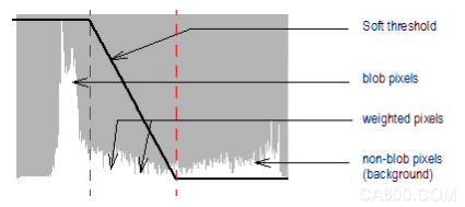
Soft thresholding provides flexibility in processing pixels in the boundary blob area. Soft thresholding covers all pixel values. Once processed, pixels within the threshold range are output as weighted pixels. Weighted pixels are used to calculate the blob result in proportion to their value within the threshold range. The range of values ​​within the soft threshold is user-defined and corresponds to the difference between the maximum and minimum thresholds.
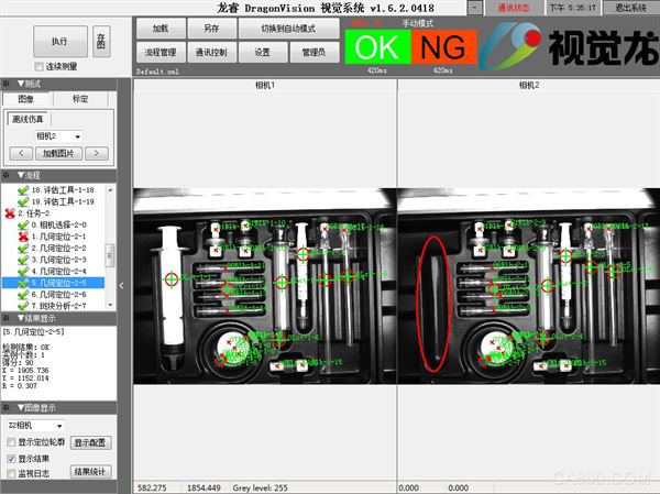
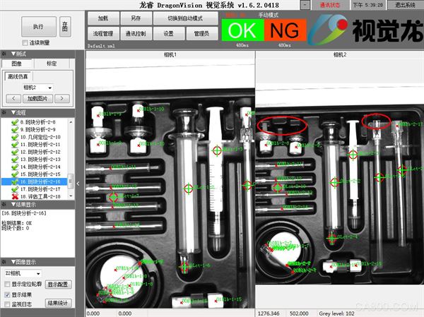
3. Camera offline simulation of test results
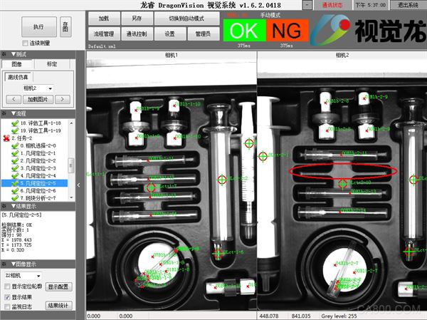 ,
,
4. Conclusion
Longrui standard vision software has friendly interface and simple operation. In addition to defect detection, it can also be used for color search, presence or absence judgment, shape judgment, identification detection, appearance detection, 3D online detection, line scan detection, positioning, geometric measurement, intelligent learning, robot guidance, etc.
Manual Pulse Generator
A manual pulse generator (MPG) is a device normally associated with computer numerically controlled machinery or other devices involved in positioning. It usually consists of a rotating knob that generates electrical pulses that are sent to an equipment controller. The controller will then move the piece of equipment a predetermined distance for each pulse.
The CNC handheld controller MPG Pendant with x1, x10, x100 selectable. It is equipped with our popular machined MPG unit, 4,5,6 axis and scale selector, emergency stop and reset button.
Manual Pulse Generator,Handwheel MPG CNC,Electric Pulse Generator,Signal Pulse Generator
Jilin Lander Intelligent Technology Co., Ltd , https://www.jilinlandermotor.com