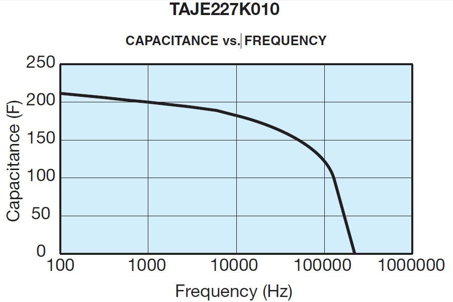
We know that each capacitor has its frequency characteristics. What is the frequency characteristic of the AVX tantalum capacitor? The AVX tantalum capacitor decreases with increasing frequency, until the resonance reaches (usually 0.5 - 5MHz). The rating between the two).
In addition to the resonant frequency of the device becomes sensible. In addition to the 100kHz capacitor continues to drop. The following takes the 220UF 10V specification of the AVX chip tantalum capacitor E as an example to illustrate the frequency characteristic of the tantalum capacitor AVX tantalum capacitor temperature characteristic curve.
Before introducing the temperature characteristics of AVX tantalum capacitors, we must understand the following two basic concepts:
Rated capacity (CR)
This is the rated capacitance. For 钽OxICap? capacitors, the capacitance measurement is at 25 ° C. The equivalent series circuit uses a measuring bridge to provide a 0.5V RMS 120Hz sinusoidal signal, harmonics and 2.2Vd.c.
Capacitance tolerance
This is the allowable deviation capacitance rating of the actual value.
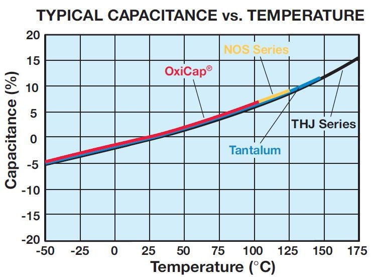
The temperature characteristics of the AVX tantalum capacitor.
The capacitance of the tantalum capacitor changes with temperature. This change is itself dependent on the magnitude of the rated voltage and capacitance to a small extent. It can be seen from the temperature graph below that the capacity of tantalum and tantalum capacitors rises with increasing temperature over the operating temperature range.
Loss tangent (TAN).
This is a measure of the energy loss in the capacitor. It is expressed in tan, which is the power loss of the capacitor whose reactive power is divided into a specified set of sinusoidal voltage frequencies. Terms also used are power factor, loss factor and dielectric loss. COS(90 - ) is the true power factor. "Measure the Tan Bridge using measurements to provide a 0.5V RMS 120Hz sinusoidal signal.
Dissipation and temperature
A typical curve performance of the dissipation coefficient as a function of temperature. These plots are the same capacitors as O and OxiCap.
The tangent loss angle (TAN) of the dissipation factor measurement, expressed as a percentage. The measurement DF is carried out to measure the bridge supply with a 0.5V RMS 120Hz sinusoidal signal, free harmonics and bias 2.2Vdc. The DF values ​​are temperature and frequency dependent. Note: The ratings table for the maximum DF values ​​allowed for surface mount products is important. Please note that these limits are met by soldering on the rear substrate of the component.
Frequency dependence of dissipation factor
As the frequency increases, the loss factor shows the impedance of the AVX tantalum capacitor (Z), which is the same as the typical curve of the OxiCap tantalum capacitor.
This is the ratio of current to voltage at the specified frequency. Three factors contribute to the impedance of the tantalum capacitor; the value of the resistor and capacitor of the semiconductor layer and the inductance of the electrodes and leads. The inductance caused at high frequencies becomes a limiting factor. The behavior of temperature and frequency determines the impedance behavior of these three factors. The impedance Z. impedance is at 25 ° C and 100 kHz.
The equivalent series resistance of the AVX tantalum capacitor ESR.
Resistance losses occur in all feasible form capacitors. These are all made up of several different mechanisms, including resistive components and contacts.
Defect current path within the viscous force medium and production bypass. In order to express the effect on these losses, the frequency dependence and available relationship of the ESR. ESR of the capacitor are considered; ESR = Tan δ2πfC where F is the frequency of Hertz and C is the capacitance farad. The ESR is measured at 25 ° C and 100 kHz. ESR is one of the factors of impedance and becomes a dominant factor at high frequencies (100 kHz and above). As a result, the ESR and impedance are almost the same, and the impedance is only slightly higher.
The impedance of the AVX tantalum capacitor and the frequency dependence of the ESR.
Both ESR and impedance increase with frequency. At lower frequency values ​​as an additional contribution to the divergence impedance (due to the reactance of the capacitor) becomes more important. In addition to the 1MHz (and the resonant point of the over-capacitance) the impedance increases again due to the inductance and capacitance.
Typical ESR and impedance values ​​are similar to that of tantalum oxide materials, and thus the same graphs are effective for tantalum capacitors and OxiCap capacitors.
The AVX agent talks about the impedance vs. temperature of the tantalum capacitor and the ESR. At 100 kHz, the impedance and ESR behave the same, and the typical curve decreases with increasing temperature.
Surge voltage of tantalum capacitor
The voltage and current surge capability that AVX tantalum capacitors can withstand is limited. This is based on the common property of all electrolytic capacitors. A high enough electrical stress will pass through the dielectric, destroying the medium. For example, a 6 volt tantalum capacitor has an electric field of 167 kV/mm when operating at rated voltage. It is therefore important to ensure that the voltage across the capacitor terminals never exceeds the specified surge voltage rating. The semiconductor manganese dioxide used as the tantalum capacitor negative plate layer has self-healing ability.
However, this low resistance is limited. In the case of a low impedance circuit, the capacitor may be broken down by the inrush current. The step-down capacitor increases the reliability of the component. The rated voltage is used on common voltage traces. When the low-impedance tantalum capacitor is rapidly charged or discharged in the circuit, the protection resistance is recommended to be 1Ω/V. If this requirement is not met, the tantalum capacitor should be used with a step-down factor of 70%. In this case, a higher voltage ratio may be required as a single capacitor. The A series combination should be used to increase the equivalent voltage of the operating voltage:
For example, two 22μF25V series sections are equivalent to a portion of 11μF 50V.
It refers to the highest voltage that the capacitor can withstand the minimum series resistance of 33 Ohms (CEC country 1KΩ) in a short time. Surge voltage, up to 10 times the voltage in an hour at room temperature and up to 30 seconds. Surge voltage is only used as a reference parameter and cannot be used as a basis for circuit design. During normal operation, the capacitor should be charged and discharged periodically.
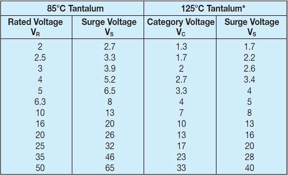
The value of the surge voltage is different at different temperatures. At 85 degrees and below, the classification voltage VC is equal to the rated voltage VR, the surge voltage VS is equal to 1.3 times the quota voltage VR; at 85 to 125 degrees, the classification voltage VC is equal to 0.66 times the rated voltage VR, and the surge voltage VS is equal to 1.3 times the classification voltage VC.
Reverse voltage of tantalum capacitor
The reverse voltage of the AVX tantalum capacitor is strictly limited as follows:
Up to 10% rated DC operating voltage at 1.0V 25° C
Up to 3% rated DC operating voltage at 0.5V 85° C
Up to 1% rated DC operating voltage at 0.1V 125°C
The reverse voltage values ​​are based on the highest voltage value of the tantalum capacitor at any time. These limitations are assumed to be the working life of the tantalum capacitor polarized light in most of its correct orientation. Their purpose is to cover short-term reversals such as a small portion of an impressive waveform that occurs during switching transient polarity. Continuous application of a reverse voltage causes polarization and will result in increased leakage current. Under what circumstances continuous reverse voltage application may occur. Two similar capacitors should be connected with a negative termination back-to-back configuration. In most cases this combination will have half of the capacitance of a nominal capacitor, whether it is a capacitor. In isolated pulse conditions or in the first few cycles, the capacitor may be the full nominal value of the method. The design of the reverse voltage level covers the small level of the tour to make the wrong conditions. The referenced value is not intended to cover continuous reverse operations.
The superimposed AC voltage of the tantalum capacitor (Vr.ms) ------ also known as the ripple voltage
This is the largest rms AC voltage; superimposing a SAR voltage can be applied to a capacitor. The sum voltage and peak superimposed AC voltage in Washington must not exceed this category voltage.
The forming voltage of the tantalum capacitor.
This is the voltage formed by anodization. "The thickness of this oxide layer is a factor that forms a voltage proportional to a capacitor and is set at the rated voltage.
Pharmaceuticals,2-Methyl- Propanoic Acid Monohydrate Price,2-Methyl- Propanoic Acid Monohydrate Free Sample,Pure 2-Methyl- Propanoic Acid Monohydrate
Zhejiang Wild Wind Pharmaceutical Co., Ltd. , https://www.wild-windchem.com